SPX-7200 Series Operations Manual Suprex® Reader Extender - Ethernet SPX-7200 EXP-2000 SPX-7200_MAN_082112
Cypress Suprex® SPX-7200 Series Overview This manual covers the operation and setup of the Cypress Suprex® SPX-7200 Ethernet series units. Overview: The SPX-7200 series of Ethernet solutions provides an Ethernet bridge from Card Readers with gates or door hardware to most access control manufacturers panels. The SPX or Suprex® products include both the remote ( Door/Gate ) unit and the central ( AC Panel ) unit.
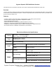
External connections and DIP Switch Settings 1 - 8 to 16 VDC In 2 - Ground 1- Relay 4 N.O. 2- Relay 4 Com 3 - Relay 4 N.C. 4 - Relay 3 N.O. 5 - Relay 3 Com 6 - Relay 3 N.C. 7 - Ground 8 - Aux out 9 - R2 in 10 - R1 in SPX-7200 Central Status LED 1 - exp (+) 2 - exp (-) 3 - +5 VDC out 4 - Prog Res 4 5 - Prog Res 3 6 - LED In 7 - D1/Data out 8 - D0/Clk out 1 - 8 to 16 VDC In 2 - Ground SPX-7200 Remote Status LED 1- Relay 2 N.O. 2- Relay 2 Com 3 - Relay 2 N.C. 4 - Relay 1 N.O.
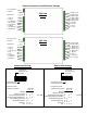
Quick Reference For Typical Connections SPX-7200 Series Central DC Power Supply +8 to +16 VDC Ground Diagnostic LED Access Control Panel R1 Input Controls Strike on Remote LED In D1/Data Out D0/Clock Out R1 IN See page 14 for other strike control options SPX-7200 Series Remote DC Power Supply +8 to +16 VDC Ground Diagnostic LED R1 N.O. R1 Com R1 N.C.
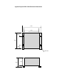
Cypress Suprex® SPX-7200 Enclosure Dimensions 4.45 3.15 0.80 3.08 0.80 ø0.20 X 4 2.00 1.
Cypress Suprex® SPX-7200 Series - Indicators and Operating Modes LED Diagnostic Indicator: The LED Diagnostic indicator provides information on the operational status of the unit. If the units are not communicating, viewing the diagnostic indicator LED’s may help to determine the nature of the problem.
Bench Testing: Before installing the units in the field they should be assembled and tested at a convenient “Bench top” location. This will make it easier to verify / change settings and check operation when both units are visible at the same time. It is also a chance to become familiar with the system if this is the first time using the Suprex® system. It is much more difficult to setup and test the units when they are several thousand feet apart. 1.
Cypress Suprex® SPX-7200 Changing to UDP The Cypress SPX-7200 is factory set to use TCPIP. To change to UDP use the Lantronix web interface with the following settings. Channel 1 Remote Port = 10001 Remote Host = 0.0.0.0 Use Broadcast = Checked Device Address Table = All = 0 - Click Ok - Click Apply Settings.
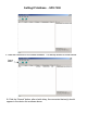
Setting IP Address - SPX-7200 1. Start the Lantronix XPort Installer software. The startup screen is shown above. Search Button 2. Click the “Search” button, after a brief delay, the connected device(s) should appear in the device list as shown above.
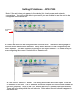
Setting IP Address - SPX-7200 Note: If the unit does not appear in the device list, check power and network connections. You will not be able to proceed if you are unable to see the unit to be configured in the device list. Device in List 3. Select the device to be configured with a mouse click. The device will highlight in blue as shown above when selected. Verify which device is to be configured by the MAC address. The MAC address is printed on the Xport module. i.e.
Setting IP Address - SPX-7200 Once both units have had their IP addresses set, it will be necessary to tell the CENTRAL unit the address of the Remote unit. 5. After the IP addresses have been assigned to both units, select the CENTRAL unit in the device list.
Setting IP Address - SPX-7200 7. You should now have an open window like this. Press the ENTER key to enter setup mode. 8. A list of options will be presented, select Option #1 (Channel 1).
Setting IP Address - SPX-7200 9. All of the parameters will have been set as factory default, it will be necessary to set the address of the REMOTE unit in the Channel 1 parameters. In the example above, the parameters for the factory default settings have been entered. Keep in mind that this is the CENTRAL unit and we are entering the address of the REMOTE unit. 10.
Cypress Suprex® SPX-7200 Series - Door Strike and LED I/O Note: The LED and Door Strike operation of the Ethernet Suprex® differs from previous Suprex® versions. To activate the relay on the Remote unit, connect as shown below. These connections can be used to allow the Remote relay to operate a DOOR STRIKE, GATE, or other locking hardware. Refer to following pages in this document for details of each I/O operation and connection. There are two relays available for accessory outputs at the Remote end.
Cypress Suprex® SPX-7200 Series - Door Strike and LED I/O The Cypress Suprex® SPX-7200 Series provides additional data channels to support access control hardware such as door strikes, tamper alarms, request to exit status, etc. These signals are sent to and from the Remote and Central units without the need to run additional wiring. The accessory control I/O use active low inputs. When the inputs are floating (nothing connected) the associated output will be set to a high level.
Cypress Suprex® SPX-7200 Series - Relay Controls Suprex® Central Suprex® Central Relay 2 IN Relay 1 IN Input Signal Input Signal Red arrow denotes direction of command signal Relay 2 N.O. Relay 2 Com Relay 2 N.C. Suprex® Remote Relay 1 N.O. Relay 1 Com Relay 1 N.C.
Cypress Suprex® SPX-7200 Series - Relay Controls Relay 4 N.O Relay 4 Com Relay 4 N.C. Suprex Central Relay 3 N.O. Relay 3 Com Relay 3 N.C. Suprex Central Contact Outputs Contact Outputs Red arrow denotes direction of command signal Suprex Remote Suprex Remote Relay 4 IN Relay 3 IN Input Signal (5Volts DC Maximum) Input Signal (5Volts DC Maximum) Relay 3 functions as an Alarm relay and monitors the condition of the communication link between the Central and Remote units.
SPX-XXXX Application Note Using Supervised Contacts with the SPX-series Extenders Applies to the following products: SPX-5501, SPX-5601, SPX-5521, SPX-5621, SPX-7400, SPX-7410, SPX-7200, SPX-7500, All RIM series products. This application note describes the connections necessary to convey supervised contact status over a Suprex® communication link. The configurations described in this app note should apply to most panels that utilize supervised contacts.
SPX-7200 Setup - Using Expansion Modules Before using EXP-2000 Expansion modules with the SPX-7200 system, it will be necessary to perform a short configuration process. This process determines if the 7200 will utilize expansion modules, and if so, how many will be used with the system. Each SPX-7200 link can support up to 8 expansion modules. SPX-7200 units are shipped in the factory default condition. Factory default units will be setup to function as SPX-7200 units without expansion modules.
Cypress Suprex Ethernet Solution with Wiegand expansion modules Door / Parking Gate - Typical SPX-7200R (1) EXP-2000R (2) EXP-2000R (3) EXP-2000C (3) ACS EXP-2000C (2) SPX-7200C (1) Card Reader Wiegand Data RS-485 Link - Multi-drop Control and I/O
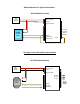
Cypress Suprex® Series - Wiegand Expansion Module Panel “Central” interface DC Power Supply +8 to +16 VDC Ground EXP(+) EXP(-) Access Control Panel LED In D1/Data Out D0/Clock Out 8 to 16 VDC In Ground 485(+) 485(-) +5 VDC Out Prog Res 4 Prog Res 3 LED Input D1/Data Out D0/Clock Out * EXP-2000 Central Unit SPX-XXXX Central R1 IN RLY4 N.O. RLY4 Com RLY4 N.C. RLY3 N.O. RLY3 Com RLY3 N.C.
Cypress Suprex® Series - Wiegand Expansion Module Reader/Door “Remote” interface DC Power Supply 8 to 16 VDC In Ground EXP (+) EXP (-) SPX-XXXX Remote R1 N.O. R1 Com R1 N.C. LED Out D1/Data In D0/Clock In Card Reader 8 to 16 VDC In Ground 485(+) 485(-) +5 VDC Out RLY4 Input (5V) RLY3 Input (5V) LED Output D1/Data Input D0/CLK Input * EXP-2000 Remote Unit RLY2 N.O. RLY2 Com RLY2 N.C. RLY1 N.O. RLY1 Com RLY1 N.C.