RAMSET www.ramsetinc.
RAMSET www.ramsetinc.
RAMSET Important Safety Requirements & Instructions....................................................................................1 Responsibilities of Installers and Technicians.....................................................................................2 Important Safety Requirements by UL Standards...............................................................................3 Classes of Vehicular Gate Operators................................................................................
RAMSET Responsibilities of installers and technicians installation RAM 30-30 • Read and understand the instruction manual before attempting any installation. • Do not exceed the equipment specifications. • Insure a safe and proper installation. • Install this equipment in accordance with the Ul 325 specifications. • Make sure to eliminate any pinch points existing on the installation. (ie. Rollers, arms…etc.) • ramset gate operators must be installed by a trained technician.
RAMSET IMPORTANT SAFETY REQUIREMENTS BY UL STANDARDS a) Install the gate operator only when: 1. The operator is appropriate for the construction of the gate and the usage Class of the gate, 2. All openings of a horizontal slide gate are guarded or screened from the bottom of the gate to a minimum of 4 feet (1.22 m) above the ground to prevent a 2 1/4 inch (57.
RAMSET Classes of vehicular gate operators RAM 30-30 Vehicular horizontal slide-gate operator (or system) - A vehicular gate operator (or system) that controls a gate which slides in a horizontal direction that is intended for use for vehicular entrance or exit to a drive, parking lot, or the like.
RAMSET General specifications gate traveling speed: motor: duty cycle: operating temperature: power failure release: overall dimensions: shipping weight: WARNING 20’ @ 3000 lbs Approx 90° opening in 16 sec 3/4 Hp, 1 Hp Continuous RAM 30-30 maximum gate size & Weight: -10º F to 160º F Knob Release or Battery Back Up H 27½” L 17½” W 23½” 200 lbs Do not exceed the specifications. The warranty on your unit will be void if the installation exceeds the recommended specifications.
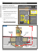
RAMSET Installation specifications RAM 30-30 Concrete PAD CONSTRUCTION: Steel Square Tubing 4x4 Dimensions given for the pad are based on soil bearing shear of 2000 P.S.F. These figures may have to be adjusted depending on local soil conditions. 1. Construct form for mounting pad according to dimensions shown in Figure 1 and 2. Outside Property STANDARD INSTALLATIONS CONDUIT FOR ELECTRIC POWER CONDUIT FOR COMMUNICATION CONDUIT FOR MASTER/SLAVE 2.
RAMSET hookup electrical power GATE TRAVEL ADJUSTMENT RAM 30-30 Figure 4 Outlet Leads Note: 15 amp wires connected to independent breaker. Gate travel is adjusted by loosening the limit Cams and adjusting them until proper gate travel has been achieved. Standard Installation for Gates from 8’ to 16’ in Length Do not exceed the specifications. The warranty on your unit will be void if the installation exceeds the recommended specifications.
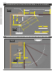
RAMSET STANDARD INSTALLATION FOR GATES FROM 16’ TO 20’ IN LENGTH Steel Square Tubing 4x4 Outside Property 16’ to 20’ Maximum Gate Length RAM 30-30 50” Gate Closed Gate Rotation Center (hinge) 24” 42” Supplied Bracket 43 1/4” 33 1/4” 76 1/2” 32” SHORT ARM DIM. Inside Property 42” OPERATOR PIvOT ShAFT CENTER LONG ARM DIM. Space required for a standard Gate in the open position Outside Property 15 1/4” Inside Property 4’ 4 ft.
RAMSET SENSOR INSTALLATION WARNING A non-contact sensor (photoelectric sensor or equivalent) and a contact sensor (edge device or equivalent) is required on each individual installation to comply with UL325. Reversing Loops on the ground floor, prevents gate from closing when vehicle is in loop area. Exit Loops on the ground floor, opens gate when vehicle crosses loop area. Photoelectric Safety Sensor (Photo Eye) prevents the gate from closing when any object interrupts the beam. Figure 10 www.
RAMSET PUSHBUTTON CONTROLS RAM 30-30 Three pushbuttons are located under the dip switches for operation of the gate (see Figure 11). The opening, stop and closing buttons can be utilized to set limit switches and verify proper system operation when installing or servicing an operator. L.E.D.’s light up when opening, Closing or Stopped Opening: Pressing this button will cause the gate to open. Stop: Pressing this button will cause the gate to stop moving.
RAMSET DIP SWITCH CONFIGURATION RAM 30-30 Figure 13 “Intelligate” Control Board DIP SWITCH "A" Dip Switch "A" 1, 2 & 3; AUTOMATIC TIMER TO CLOSE GATE ‘0’ is “OFF” Switch Dip Switch "B" 2; “PRE WARN” Used with JP2 “Relay Connections”: pins 7 & 8. Triggers a relay, for an alarm or light (not included), for 3 seconds before the gate will move in any direction.
RAMSET DIP SWITCH CONFIGURATION DIP SWITCH "C" Dip Switch "C" 1; “SECURE CLOSE” Sw. Dip Switch "C" 5; “CLOSE DELAY” One second delay on the closing of the gate. Function: RAM 30-30 OFF Normal Operation ON When power is lost, then regained, control board checks status of the gate. If open and safety devices are cleared, gate will close automatically. Dip Switch "C" 6; “OPEN DELAY” One second delay on the opening of the gate. Dip Switch "C" 7; “LEFT / RIGHT” Sw.
RAMSET SAFETY Terminal strip Connection RAM 30-30 Figure 14 For RAM 30 30 For RAM 30 30 3/4 Hp www.ramsetinc.
RAMSET Terminal strip Connections RAM 30-30 Terminal # 1 - Common: Low voltage common. Terminal # 2 - Rev loop: Stops the gate from closing. If the gate is open, it holds the gate open. If the gate is closing, it stops and reopens the gate. If the gate is closed, the gate will remain closed. The function can be altered with Dip Switch “C” 4 (see “Dip Switch Configuration”). Used with loop detectors, photo eyes, safety edges…etc. Becomes active with a closed contact to common.
RAMSET ramset “Intelligate” Control Board Ramset’s “Intelligate” Control Board works with Sliding, Swinging and Overhead vehicular gate operators. It is controlled by a programmable microprocessor that reads and precisely executes all functions of the Control Board. The Control Board is powered by a separate mounted 24 VAC transformer. This allows no necessary board modifications between 110 VAC and 220 VAC single-phase applications.
RAMSET Wire board connections RAM 30-30 JP9 - Input Power: 1,2) 24 VAC power. Connection from external transformer to power Control Board. JP2 - Relay Connections: JP3 - 3 Button: 1) Open 2) Stop 3) Close 4) Common Used with a 3-button station to open, stop, and close the gate. The open and close are normally open connections and the stop is a normally closed connection, remove jumper wire when connecting 3 button station.
RAMSET Parts Diagram Figure 16 44 46 RAM 30-30 11 41 45 10 42 28 29 15 38 43 16 35 27 39 17 8 32 34 6 33 2 5 36 34 21 39 20 18 40 22 3 24 31 13 7 19 37 23 14 4 12 25 26 1 9 13 32 www.ramsetinc.
RAMSET bill of materials for: RAm 30-30 Part # 1 800-00-06 2 800-02-08 RAM 30-30 Item 18 PART DESCRIPTION 3/4 HP 1 HP Chassis 1 1 Gear Reducer - Size 70, Ratio 60:1 1 1 1 3 800-04-12 Motor, Standard - 120VAC 3/4 HP 4 800-04-13 Motor, Standard - 220VAC 1HP 5 800-06-00 Sprocket - 1 1/8” - 50BS15H 1 1 6 800-08-05 Pulley, Cast Iron - 7/8” x 10” : MA100 1 1 7 800-08-45 Pulley, Steel - 5/8” x 2” : AK20 1 1 1 8 800-10-30 Belt - 4L-360 1 1 9 800-12-07 Shaft, Output -
RAMSET Item Part # 41 800-75-00 42 800-28-00 43 PART DESCRIPTION 3/4 HP 1 HP 1 1 Arm, Metal Tubing - 1” x 2” x 32” 1 1 800-28-01 Arm, Metal Tubing - 1” x 2” x 42” 1 1 44 800-54-10 Bracket, Channel - 1 3/4” x 10” 1 1 45 800-54-30 Bracket, External Gate - 1 1/2” x 12” 1 1 46 800-54-37 Bracket, Gate 1 1 ARM ASSEMBLY www.ramsetinc.
RAMSET Gate entrance Safety Precautions Not following these instructions may cause severe injury or death to persons RAM 30-30 WARNING Important Safety Instructions 1. Never let children operate or play with gate controls. Keep the controls away from children. 2. The entrance is for vehicles only. Pedestrians should use a separate entrance. 3. Always keep people, children and objects away from the gate while the gate is in operation. No one should cross the area of a moving gate. 4.
RAMSET RAM 30-30 Important information for the homeowner Ask your technician about all the features of our Use the emergency release only when the gate is Safety devices, such as reversing loops, phantom Have the technician give you a demonstration of new Ramset operator. loops, photo eyes, or miller edges must be installed on your gate before the operator may be used. Ask your technician which safety devices best suit your safety needs. not moving & power is turned off to the unit.
RAMSET TROUBLESHOOTING Table RAM 30-30 CONDITION SOLUTION POSSIBLE CAUSES NO LIGHTS ARE 'ON'. 1. Circuit breaker popped. 2. 1/2 amp. fuse blown. 3. Power supply damaged on Control Board. 1. Reset circuit breaker. 2. Replace 1/2 amp. fuse. 3. Return Control Board for repair. GATE MOVES A COUPLE OF FEET AND THEN REVERSES. 1. E.R.D. too sensitive. 1. A) for 1/2 hp motors: turn dip switch "A" 4 'On'. "EXIT" L.E.D. IS ALWAYS 'ON'. 1. Faulty accessory connected to the "Exit". 1.
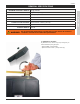
RAMSET RAM 30-30 Ramset Optional Accessories Fire Box LCD-Keypad 1,024 Codes 5,112 Event Log LCD Display 7-Day Timer Time Zones Latching Stainless Steel Faceplate Allows the fire department to open the gate in the case of an emergency. Post Mounts 1/4” angle iron flats. 3/16” square tubing legs. Used to mount the operator off the ground. Magnetic Lock Key Switch Box 12/24V DC. 1100 lb holding force. Secures the gate(s) closed. Suitable for use on Entry doors where access is restricted by a key.
9116 De Garmo Ave. Sun Valley, CA 91352 Tel: (818) 504-2533 • Fax: (818) 504-1141 www.ramsetinc.