
User Manual


5
www.ramsetinc.com
RAMSET
4"
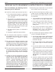
INSTALLATION SPECIFICATIONS
All Sliding Gate Operators are factory preset for (LH) Left Hand Installations.
PAD CONSTRUCTION:
Dimensions given for the pad are based on soil
bearing shear of 2000 P.S.F. These figures may
have to be adjusted depending on local soil
conditions.
1. Construct form for mounting pad according to
dimensions shown in Figure 1, 2 and 3.
2. Locate mounting pad according to dimensions
given in illustration.
3. Level top edge of form.
4. Set reinforcing bars and wire mesh.
5. Mix concrete; pour mixture into form. Level and
finish surface after pouring is complete.
6. Allow pad to cure for 48 hours, and remove
forms.
MODEL Dim "A" Dim "B"
RAM 100 11 1/2" 11 1/4"
RAM 1000 13 1/4" 8 5/8"
RAM 5500 13 1/4" 8 5/8"
Figure 1
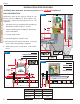
Figure 2
Figure 3
TOP VIEW
GATE
SHOWN OPEN
LH FRONT
INSTALLATION
TOP VIEW
GATE SHOWN CLOSED
LH FRONT INSTALLATION
TAIL
GATE
GATE