www.ramsetinc.
RESPONSIBILITIES OF INSTALLERS AND TECHNICIANS INSTALLATION: • READ AND UNDERSTAND THE INSTRUCTION MANUAL BEFORE ATTEMPTING ANY INSTALLATION. • DO NOT EXCEED THE EQUIPMENT SPECIFICATIONS. • INSURE A SAFE AND PROPER INSTALLATION. • INSTALL THIS EQUIPMENT IN ACCORDANCE WITH THE UL 325 SPECIFICATIONS. • MAKE SURE TO ELIMINATE ANY PINCH POINTS EXISTING ON THE INSTALLATION. (ie. ROLLERS, ARMS…etc.
RAMSET TABLE OF CONTENTS Important Safety Requirements & Instructions ……………………………………………………….. 1-2 Classes of Vehicular Gate Operators ...…………………………………………………………………. 3 Mechanical Specifications ………………………………………………………………………………... 4 Installation Specifications …………………………………………………………………………………. 5 Types of installations ……………………………………………………............................................... 6 Sensor installation & Gate Travel Adjustment ………………………………………………………......
IMPORTANT SAFETY REQUIREMENTS & INSTRUCTIONS RAMSET IMPORTANT SAFETY REQUIREMENTS & INSTRUCTIONS BY UL STANDARDS Prior to installation, the following must be observed: (per UL 325.51.8.4). f) All warning signs and placards must be installed a) Install the vehicular gate operator only when: g) For Vehicular Gate Operators utilizing a non- 1) The Vehicular Gate Operator is appropriate for the construction of the gate and the usage class of the gate.
RAMSET CLASSES OF VEHICULAR GATE OPERATORS Vehicular horizontal slide-gate operator (or system) - A vehicular gate operator (or system) that controls a gate which slides in a horizontal direction that is intended for use for vehicular entrance or exit to a drive, parking lot, or the like.
RAMSET MECHANICAL SPECIFICATIONS: MODEL: RAM 100 RAM 1000 RAM 5500 Max. Gate Length: 20 feet 45 feet 45 feet Max. Gate Weight: 700 lbs. 1000 lbs. 1500 lbs. Continuous Continuous Continuous Aerovox 65µƒ, 240 V, 50/60 HZ, protected S 1000AFC Aerovox 65µƒ, 240 V, 50/60 HZ, protected S 1000AFC Aerovox 65µƒ, 240 V, 50/60 HZ, protected S 1000AFC Residential Residential/Commercial Res./Com./Industrial Gold/Zinc plated 3/16" H.R. Metal Gold/Zinc plated 3/16" H.R.
RAMSET INSTALLATION SPECIFICATIONS All Sliding Gate Operators are factory preset for (LH) Left Hand Installations. PAD CONSTRUCTION: Figure 1 Dimensions given for the pad are based on soil bearing shear of 2000 P.S.F. These figures may have to be adjusted depending on local soil conditions. 1. Construct form for mounting pad according to dimensions shown in Figure 1, 2 and 3. 2. Locate mounting pad according to dimensions given in illustration. 3. Level top edge of form. 4.
RAMSET TYPES OF INSTALLATIONS: Figure 4 FRONT INSTALLATION GATE SHOWN Closed Tail on gate required Inside Property TAIL Outside Property Figure 5 CENTER INSTALLATION GATE SHOWN Fully Open No tail on gate required Inside Property Top View Front View WARNING: Outside Property REAR INSTALLATION GATE SHOWN Fully Open Figure 6 USE ONLY CHAIN GUARDED PULLEYS Note: This type of installation does not apply for model RAM 100 No tail on gate required Inside Property Wall Top View Hidden Wall Front V
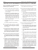
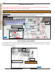
RAMSET SENSOR INSTALLATION Ramset Gate Operators should not be installed without non-contact sensing devices such as Loop Detectors, photo electric sensors or the equivalent. A non-contact sensor (photoelectric sensor or equivalent) and a contact sensor (edge WARNING: device or equivalent) is required on each individual installation to comply with UL325. Reversing Loops on the ground floor, prevents gate from closing when vehicle is in loop area.
RAMSET PUSHBUTTON CONTROLS Three pushbuttons are located under the dip switches for operation of the gate (see Figure 9). The opening, stop, and closing buttons can be utilized to set limit switches and verify proper system operation when installing or servicing an operator. Opening Pressing this button will cause the gate to open. L.E.D.’s light up when function is activated Figure 9 "Intelligate" Control Board Stop Pressing this button will cause the gate to stop moving.
RAMSET DIP SWITCH CONFIGURATION Figure 11 "Intelligate" Control Board DIP SWITCH "A" Dip Switch "A" 1, 2 & 3; AUTOMATIC TIMER TO CLOSE GATE Dip Switch "B" 3; “CONSTANT WARN” ‘0’ is “OFF” (Constant warning when gate is in motion). Switch ‘1’ is “ON” 1 2 3 Gate Open Duration: Sw. 1 1 1 60 seconds OFF No effect.
DIP SWITCH CONFIGURATION RAMSET DIP SWITCH "C" Dip Switch "C" 7; “LEFT / RIGHT” Dip Switch "C" 1; “SECURE CLOSE” Sw. Function: OFF Normal Operation ON When power is lost, then regained, control board checks status of the gate. If open and safety devices are cleared, gate will close automatically. Sw. Function: OFF Left hand installations - All operators come factory set for left hand operation. ON Right hand installations - Reverses motor & limit switches without moving any wires.
RAMSET TERMINAL STRIP CONNECTION Figure 12 11 www.ramsetinc.
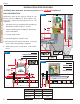
RAMSET TERMINAL STRIP CONNECTIONS plied to the alarm connection, for 6 minutes and the control board will not accept any commands. After the 6 minutes the 24 VDC is removed from the alarm connection and the board resets to normal operation. Terminal # 1 - COMMON: Low voltage common. Terminal # 2 - REV LOOP: Stops the gate from closing. If the gate is open, it holds the gate open. If the gate is closing, it stops and reopens the gate. If the gate is closed, the gate will remain closed.
RAMSET RAMSET “INTELLIGATE” CONTROL BOARD Introduction: sary board modifications between 110 VAC and Ramset’s “Intelligate” Control Board works 220 VAC single-phase applications. with Sliding, Swinging and Overhead vehicular functions of the Control Board are: 0 - 60 seconds gate operators. It is controlled by a program- automatic close timer, self adjusting E.R.D.
RAMSET WIRE BOARD CONNECTIONS JP9 - Input Power: 1,2) 24 VAC power. Connection from external transformer to power Control Board. JP3 - 3 Button: 1) Close 2) Stop 3) Open 4) Common Used with a 3-button station to open, stop, and close the gate. The open and close are normally open connections and the stop is a normally closed connection, remove jumper wire when connecting 3 button station. JP7 - Master/Slave plug: 1) A 2) B 3) Common 4) 5 VDC 5) 24 VAC.
RAMSET PARTS DIAGRAM Figure 14 24 63 23 4 8 70 19 18 29 9 15 31 38 36 35 37 32 73 26 28 27 3 25 33 38 26 7 13 14 5 21 34 25 64 42 20 39 72 6 1 16 61 62 41 15 11 40 www.ramsetinc.
RAMSET PARTS DIAGRAM Figure 15 47 4 58 38 70 69 53 24 68 52 23 51 59 32 67 66 30 37 42 69 35 26 29 21 22 71 10 48 62 46 32 33 61 38 60 17 34 65 64 54 50 56 25 49 45 14 43 57 36 72 39 28 27 41 40 44 73 55 5 25 36 www.ramsetinc.
RAMSET BILL OF MATERIAL FOR: RAM 100 • RAM 1000 • RAM 5500 17 ITEM PART # PART DESCRIPTION RAM 100 RAM 100 RAM 5500 1 50-001 3/16" Hot Rolled Metal Chassis 1 2 50-011 Board Metal Cover 1 3 50-024 Speed Reducer Size 43:30:1 Ratio 1 4 50-031 1/2 hp 115 VAC Electric Motor 1 1 5 50-039 20 Pin Edge Connector 1 1 1 6 50-041 1/2" x 8 1/2" Limit Switch Shaft 1 7 50-046 41 b 12 x 1/2" Sprocket 1 8 50-047 41 b 21 Clutch Release Sprocket 1 9 50-057 2" UHMW Idler Pulley 1
RAMSET BILL OF MATERIAL FOR: RAM 100 • RAM 1000 • RAM 5500 ITEM PART # PART DESCRIPTION 45 50-240 46 47 RAM 100 RAM 1000 RAM 5500 3/16" Hot-Rolled Metal Chassis 1 1 50-242 Speed Reducer Size 60 1 1 50-244 Polyethylene Cover 1 1 48 50-245 Limit Switch Chain 1 1 49 50-246 1" x 7" Limit Switch Shaft 1 1 50 50-247 3/4" Sealed Ball Bearings 2 2 51 50-248 4 pin Disc Release 1 1 52 50-249 1" Arbor release 1 1 53 50-250 41 b 27d Clutch Release Sprocket 1 1 54 50-2
RAMSET GATE ENTRANCE WARNING: 1. Never let children operate or play with gate controls. Keep the controls away from children. 2. The entrance is for vehicles only. Pedestrians should use a separate entrance. 3. Always keep people, children and objects away from the gate while the gate is in operation. No one should cross the area of a moving gate. 4. All opening devices, (such as a keypad, cardreader…), should not be installed close to the gate, where the gate could possibly cause injury. 5.
RAMSET TROUBLESHOOTING TABLE CONDITION SOLUTION POSSIBLE CAUSES NO LIGHTS ARE 'ON'. 1. Circuit breaker popped. 2. 1/2 amp. fuse blown. 3. Power supply damaged on Control Board. 1. Reset circuit bleaker. 2. Replace 1/2 amp. fuse. 3. Return Control Board for repair. GATE MOVES A COUPLE OF FEET AND THEN REVERSES. 1. E.R.D. too sensitive. 1. A) for 1/2 hp motors: turn dip switch "A" 4 'On'. "EXIT" L.E.D. IS ALWAYS 'ON'. 1. Faulty accessory connected to the "Exit". 1.