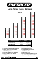
Long-Range Barrier Sensors Manual Model E-9626-2B190Q E-9643-4B190Q E-9661-6B190Q E-9679-8B190Q 4 Different programmable frequencies Range: Up to 190ft (60m) outdoor, 380ft (120m) indoor End caps swivel for easy installation Built-in heater for cold weather operation # of Beams 2 pairs 4 pairs 6 pairs 8 pairs Length 26” (66cm) 43” (109cm) 61” (155cm) 79” (201cm) Built-in tamper switches Programmable trigger options Form C relay output Weatherproof IP65 AGC circuits ensure operation in
ENFORCER Long-Range Barrier Sensors Table of Contents: Introduction ............................................ 2 Parts List ................................................ 2 Features ................................................. 3 Specifications ......................................... 3 Dimensions ............................................ 4 Swivel Housing ....................................... 4 Sample Applications ............................... 4 Overview – Inside the Sensor ................
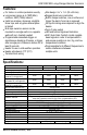
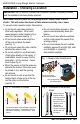
ENFORCER Long-Range Barrier Sensors Features: For indoor or outdoor perimeter security Long sensor range up to 190ft (60m) outdoors, 380ft (120m) indoors Install on windows, doorways, skylights, fence tops, and any place where space is limited End caps swivel so sensor can be mounted on a single wall or on opposite walls with no L-bracket needed Programmable immediate trigger on simultaneous breaking of beams, or trigger after a single pair of beams is broken for at least 2 seconds Heater for use in cold w
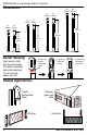
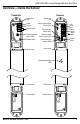
ENFORCER Long-Range Barrier Sensors Dimensions: 17/8” 21/4” (49mm) (55mm) 17/8” 21/4” (49mm) (55mm) 17/8” 21/4” (49mm) (55mm) 17/8” 21/4” (49mm) (55mm) 79” (201cm) 61” (155cm) 43” (109cm) 26” (66cm) E-9626-2B190Q E-9643-4B190Q Swivel Housing: E-9661-6B190Q 1. Remove cap 2. Loosen swivel head screw Each sensor is built with a swivel housing for flexible installations and simple alignment. To use, twist the beams up to 90. 3. Turn sensor to desired position E-9679-8B190Q 4.
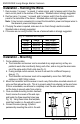
ENFORCER Long-Range Barrier Sensors Overview – Inside the Sensor: Transmitter Receiver Rubber wire hole Power Ground Tamper output Channel selection switch (SW2) Tamper switch Swivel screw Rubber wire hole Beam trigger program jumper (JP2) Response time switch (SW1) Beam alignment buzzer jumper (JP1) Channel selection switch (SW2) N.C. COM N.O. Power Ground Tamper output Tamper switch Swivel screw Red alignment/trigger LED Swivel screw Tamper switch SECO-LARM U.S.A., Inc.
ENFORCER Long-Range Barrier Sensors Installation – Choosing a Location: IMPORTANT: Do not connect to power until the sensor has been completely installed and the installation has been double-checked. When used outdoors, place the Long-Range Barrier Sensor under a roof or shelter. This will reduce the chance of false alarms caused by rain or snow. To prevent erratic operation and/or false alarms: Do not mount near trees, bushes or other leafy vegetation.
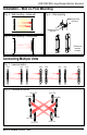
ENFORCER Long-Range Barrier Sensors Installation – Wall vs. Pole Mounting Fig. 4 – Wall mounting – Same wall Fig. 6 – Pole mounting Machine screw (4x25 mm) Machine screw (4x6 mm) Fig. 5 – Wall mounting – Facing walls (Pole-mount brackets included) Connecting Multiple Units Fig. 7 – Linear protection CH1 CH1 CH2 CH2 CH3 CH3 CH4 CH4 TX RX TX RX TX RX TX RX Fig. 8 – Perimeter protection CH 3 (TX) CH 4 (RX) CH 1 (RX) CH 2 (TX) SECO-LARM U.S.A., Inc.
ENFORCER Long-Range Barrier Sensors Installation – Running the Wires 1. Run six wires (1 x power, 1 x ground, 2 x alarm signal, and 2 x tamper switch) from the alarm control panel to the receiver of the sensor. Shielded cable is strongly suggested. 2. Run four wires (1 x power, 1 x ground, and 2 x tamper switch) from the alarm control panel to the transmitter of the sensor. Shielded cable is strongly suggested.
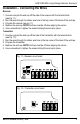
ENFORCER Long-Range Barrier Sensors Installation – Connecting the Wires Receiver 1. Unscrew and pull the end cap off the side of the receiver with the terminal block (see Fig. 11). 2. Run the wires through the rubber wire hole in the top corner of the back of the end cap. 3. Program the receiver (see pg. 11). 4. Replace the end cap. NOTE: End cap must be off when aligning the sensor. 5. Use a screwdriver to tighten the screws holding the end cap in place. Transmitter 1.
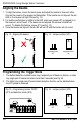
ENFORCER Long-Range Barrier Sensors Aligning the Beams 1. To align the beams, loosen the swivel screw and adjust the beams to face each other. Connect the power to the receiver and transmitter. If the beams are not aligned, the red LED on the receiver will light ON (see Fig. 13). 2. For audible confirmation in addition to the LED, make sure jumper JP1 is plugged in on the receiver’s circuit board. If the beams are not aligned, the receiver’s buzzer will sound. To disable this feature, remove JP1 (see Fig.
ENFORCER Long-Range Barrier Sensors Programming the Barrier Sensor Fig. 17 – Programming the response time (SW1) Receiver circuit board 150ms 300ms 450ms 600ms Fig. 18 – Programming the sensor beam channel frequency (SW2) Transmitter circuit board Receiver circuit board CH1 CH2 CH3 CH4 Triggering the Barrier Sensor Fig. 19 – Ways to trigger the sensor Any two adjacent pair tripped Response time: programmable 150/300/450/600ms SECO-LARM U.S.A., Inc.
ENFORCER Long-Range Barrier Sensors Troubleshooting: Receiver LED never turns ON and the buzzer never sounds Test the power and ground wire with a voltage meter to ensure power is connected and is of the correct voltage Buzzer does not sound if the sensor is triggered If jumper J1 is plugged in, this indicates that the beams are not aligned If jumper J1 is not plugged in, buzzer should never sound Receiver LED is ON and the buzzer sounds all the time Realign the transmitter and receiver Does