DIAL CODE SERIES O W N E R S M A N U A L Telephone entry systems with two line large LC or VF displays with BUILT-IN surge suppression VISIT US ON THE WEB www.chamberlain.
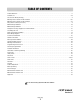
TABLE OF CONTENTS Product Overview . . . . . . . . . . . . . . . . . . . . . . . . . . . . . . . . . . . . . . . . . . . . . . . . . . . . . . . . . . . . . . . . . . . . . . . . . . . . . . . 2 Resident Use . . . . . . . . . . . . . . . . . . . . . . . . . . . . . . . . . . . . . . . . . . . . . . . . . . . . . . . . . . . . . . . . . . . . . . . . . . . . . . . . . 3-4 Screen Saver Mode (VF Only) . . . . . . . . . . . . . . . . . . . . . . . . . . . . . . . . . . . . . . . . . . . . . . . . . . . . . . .
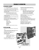
PRODUCT OVERVIEW STANDARD FEATURES • Two line LC or VF Directory. – Names listed in Directory in alphabetical order. • Memory capacity: 25, 50, 150, 250, 500, 1000 names. • User-friendly programmability via built-in alpha-numeric keyboard eliminates the need for user's manual. • Four character alpha-numeric password required to enter programming mode. • Programmable Utility keycodes for keyless entry. – 60 Utility keycodes available per system. – Time zones associated with Utility keycodes.
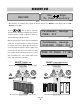
RESIDENT USE Use Keys To View Directory WELCOME (fig b.) (fig a.) When operating, the Telephone Entry System will alternate between the “Welcome” screen (fig a.) and the “View Directory” screen (fig b.). Use the keys to scroll up and down Fairbanks, George CODE: 012 through the names listed in the Telephone Entry System's electronic directory as shown in (fig c.) The names are (fig c.) listed in alphabetical order by last name.
RESIDENT USE USING KEYCODES AND UTILITY CODES (ACTIVE ENTRY 1 ONLY) RESIDENT 6-DIGIT KEYCODES Residents are assigned a 6-digit, personalized keycode * ACCESS GRANTED * Please Enter for accessing the facility. To use the keycode assigned, the resident must first push the key once and (fig a.) enter their keycode. The screen will display “Access Granted” (fig a.) and access will be allowed.
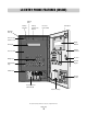
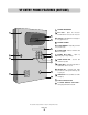
LC ENTRY PHONE FEATURES (INSIDE) Memory Card Memory Card Slot Memory Card Release Buttons Processor Power Switch Microphone Mounting Holes (4) Processor Key Release / Lock LC Display Display Window Processor Unit Stainless Steel Door Dialing Keys Key Lock External Keypad Programming Keys Parallel Port POWER External Speaker GATE RELAY DOOR RELAY Surge Suppressor Terminal Board Postal Lock Setup All components and specifications are subject to change without notice.
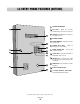
LC ENTRY PHONE FEATURES (OUTSIDE) 1 1 EXTERNAL MICROPHONE 2 KEY LOCK - Opens the Processor Containment Box to access the Processor. 3 HELP KEY - With digital voice messages to help guide the user. 4 EXTERNAL SPEAKER 5 DISPLAY WINDOW - Heavy-duty, 3/8” thick protective lens. 6 DIALING KEYS LIGHT - Lights up dialing keys for easy visibility. 7 PHONE DIALING KEYS - Used to dial residents / keycodes 8 SCROLL KEYS - Scrolls through names in alphabetical order on screen.
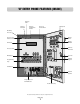
VF ENTRY PHONE FEATURES (INSIDE) Memory Card Memory Card Slot Memory Card Release Buttons Processor Power Switch Microphone Mounting Holes (4) Processor Key Release / Lock Display Hood VF Display Display Window Processor Unit Stainless Steel Door Dialing Keys Key Lock External Keypad Programming Keys Parallel Port POWER External Speaker GATE RELAY DOOR RELAY Surge Suppressor Terminal Board Postal Lock Setup All components and specifications are subject to change without notice.
VF ENTRY PHONE FEATURES (OUTSIDE) 1 1 EXTERNAL MICROPHONE 2 KEY LOCK - Opens the Processor Containment Box to access the Processor. 3 HELP KEY - With digital voice messages to help guide the user. 4 EXTERNAL SPEAKER 5 DISPLAY WINDOW - Heavy-duty, 3/8” thick protective lens. 6 DISPLAY HOOD - Reduces reflections and direct sunlight. 7 DIALING KEYS LIGHT - Lights up dialing keys for easy visibility.
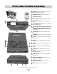
ENTRY PHONE FEATURES (PROCESSOR) 1000 Remote Access RS-485 COMMUN CATOR CARD 500 250 MEMORY CARD - Stores all programmed information. (Different memory sizes available) 2 COMMUNICATOR CARD - Card for RS485 devices. 3 POWER ON/OFF SWITCH 4 CARD RELEASE BUTTONS - Eject Cards when pressed. 5 MAIN MEMORY CARD SLOT - Holds Main Memory Card. 6 RS485 MEMORY CARD SLOT - Holds RF Communicator Card or Backup Memory.
LC MOUNTING INSTALLATION 3/4 " Mounting Holes (4) Wall 1" Installation on Wall Remove the Processor Unit from the Processor Containment Box and bolt the Processor Containment Box to the recess in the wall using the four mounting holes. Feed the power and phone lines through the knockout in the back of the box to make all wire connections.
VF MOUNTING INSTALLATION 3/4 " Mounting Holes (4) Wall 1" 6 7/8" 8 1/4" Wire Knock Outs TEL LINE 14 1/2 " TP RING RS-485 (1 +) -) GND RS-485 (2 +) -) GND RS-485 (3 (+) -) GND RS-485 (4 (+) -) GND 12V AC DC POWER NPUT Installation on Wall DOOR-NO DOOR-NC DOOR-C GATE NO GATE NC GATE C DOOR RELAY Remove the Processor Unit from the Processor Containment Box and bolt the Processor Containment Box to the recess in the wall using the four mounting holes.
DESCRIPTION OF SURGE SUPPRESSION TERMINAL BOARD 1 3 TEL LINE RS485 (1) TIP RING RS485 (4) 2 (+) (-) GND DOOR-NO DOOR-NC DOOR-C GATE-NO GATE-NC GATE-C DOOR RELAY GATE RELAY VCR RELAY VCR-NO VCR-C CHASSIS GROUND GND INPUT POSTAL/EXIT SW INPUT 4 5 12V AC/DC 3 (+) (-) GND 3 POWER INPUT POWER IN 3 RS485 (3) 12V AC/DC (+) (-) GND (+) (-) GND RS485 (2) Knockouts for Incoming Wires Removable Screw Terminal Connectors for Easy Wiring. 6 1 TELEPHONE LINE: Tip and Ring Connection.
GROUNDING THE UNIT TEL L NE TIP RING RS 485 (1) (+) () GND RS 485 (2) (+) () GND RS 485 (3) (+) () GND RS 485 (4) (+) () GND Chassis Ground 12V AC/DC POWER INPUT DOOR NO DOOR NC DOOR C GATE NO GATE NC GATE C DOOR RELAY GATE RELAY VCR RELAY VCR NO VCR C GND INPUT POSTAL/EXIT SW INPUT CHASSIS GROUND It is MANDATORY that this unit is properly grounded. The provided "chassis ground" wire must be connected to the ground rod. If unit is not grounded, lightning damage will occur.
EARTH GROUND ROD INSTALLATION Proper grounding gives an electrical charge, such as from an electrical static discharge or a near lightning strike, a path from which to dissipate its energy safely into the earth. Without this path, the intense energy generated by lightning could be directed towards the Telephone Entry System (TES). Although nothing can absorb the tremendous power of a direct lightning strike, proper grounding can protect the Telehone Entry System in most cases.
BASIC WIRING DIAGRAM Telephone Line: MUST be a dedicated line for the phone system ONLY! NOTE: Installation where fiber optic cables are present may require additional modifications from your telephone provider. Contact your provider for more information.
POSTAL LOCK INSTALLATION These parts are used only when postal access to your facility is required. The postal lock mechanism must be obtained by application to your local post office.
RS485 CONNECTION CONFIGURATIONS “Daisy Chain” wiring configuration Configuration #1 (Recommended method for superior data transmission) • Up to 31 RS485 devices supported • Maximum distance from the last RS485 device to the Telephone Entry System is 4000 Ft. • Turn “ON” the terminator switch ONLY for the last device installed in the RS485 line. • Use 22 AWG twisted pair shielded wire Turn Terminator Switch “ON” for Last Device on Wire Run Gnd + – 4000 Ft Max.
RS485 DAISY CHAIN CONNECTION EXAMPLE “Preferred Method” Remote Access RS485 COMMUNICATOR CARD TEL LINE capacity Elite Entry Phone Main Me TIP RING RS485 (1) (+) (-) GND RS485 (2) (+) (-) GND Card Slot RS485 Memory Card Slot 12V AC/DC DOOR-NO DOOR-NC DOOR-C GATE-NO GATE-NC GATE-C RS485 Card Release Button (+) (-) GND RS485 (3) DOOR RELAY GATE RELAY VCR RELAY VCR-NO VCR-C (+) (-) GND RS485 (4) POWER INPUT GND INPUT POSTAL/EXIT SW INPUT CHASSIS GROUND NOTE: To support RS485 devices yo
RS485 STAR CONNECTION EXAMPLE Use 22 AWG Twisted Pair Shielded Wire Remote Access RS485 COMMUNICATOR CARD (+) (-) Ground capacity Elite Entry Phone Main M Keypad RS485 Remote Device 1 ard Slot RS485 Memory Card Slot RS485 Card Release Button Stand-Alone Receiver RS485 Remote Device 2 NOTE: To support RS485 devices you must insert the (+) (-) Ground RF communicator card in the RS485 memory card slot BEFORE turning on the processor.
MEMORY CARD INSTALLATION Main Memory Card Slot Turn power on and insert Memory Card into Main Memory Card Slot (Main Memory Card in back slot, Backup Memory Card in front slot.) (fig a.) Push it all the way in until card “snaps” into place and the release button pops up. The screen should display the “Welcome Screen” (fig b.) RS 485 Memory Card Slot Main Memory Card Release Button (fig a.) WELCOME (fig b.) If the screen continues to display the “Insert Memory Card” screen (fig c.
WARNINGS AND PRECAUTIONS 25 0 500 Do not touch the terminals on the RAM Cards. Do not bend, drop or expose to impact. 3 2 1 6 5 4 9 8 7 P 0 O I U P HEL EX T F W D Q S A T SHIF E PAC H G E SE ERA J T R CK BAACE SP K Y ER ENT RAM PROG L M ’ N B V C X Z R BA S The Telephone Entry System is only water resistant when the Stainless Steel Door is closed and locked.
PROGRAMMING THE PROCESSOR ENTERING THE PROGRAM MODE When the Processor unit is turned on and the button is pressed, the screen will display: TO ENTER PROG MODE, Type Password >____ Type in the factory present password (7777). Press will display: . The Program Selection Screen SELECT PROG MODE: (N)Names (U)Utility If you enter the wrong password, the screen will prompt you to try again: INVALID PASSWORD (R)Retry (EXIT)Quit Press R to retry entering your password.
SELECTING PROGRAM MODE LIST OF PROGRAM MODES: page 24-26 1 Names N Program or edit Resident Names 2 Utility U Program or edit Utility Codes page 27 3 Password* P Program New Password ( recommended ) page 28 4 Clock/Timer C Program System Clock and Seven Day Timers 5 Strike Time S Program relay output time ( for 2 relays ) page 32 6 Talk TIme T Program length of Talk Time page 32 7 Greeting G Program custom Welcome Screen Message page 33 8 Volume V Program Volume level p
RESIDENT INFORMATION STEP 1 In the Program Selection Screen (fig a.), Press the SELECT PROG MODE: (N)Names (U)Utility N key. The screen will display (fig b.): PROG A NEW NAME PROG BY CODE:___ (fig a.) STEP 2 N (fig b.) You now have three options: To program by name, press the N key and the first empty code will display. To program by code, enter OR a three digit code* and press the To view or edit an existing name OR key. or code, use the keys to scroll through Directory.
TRANSMITTER/CARD PROGRAMMING STEP 6 To complete entry, press the key to return to the program selection screen. To program RF devices ( i.e. transmitters/cards etc.) continue on to Step 7. NOTE: To enable the transmitter/card programming feature, you must insert the communicator card in the “backup” slot before you turn on unit.
AREA CODES 005 PHONE NUMBER: _-___-___-____ PREFIX FIELD AREA CODE FIELD (fig a.) In special applications, it is necessary to enter area codes for Resident Phone Numbers. Area codes are entered from the Phone Number screen (fig a.). 005 PHONE NUMBER: 1-___-___-____ (fig b.) Use the key to enter the area code and prefix field (fig b.). The Prefix defaults to “1” for normal 11-digit dialing. Where necessary, you can change the prefix to any number.
UTILITY CODES A 4-digit Utility Code (numeric characters only) may be assigned to “Utility Companies” such as delivery, telephone, construction companies, water, power, etc. These utilities can use their individual code to access the premises within the time zone that you program. Each system, no matter what the memory capacity, is equipped with 60 available Utility Codes and time zones. STEP 1 In the Program Selection Screen (fig a.), U Press the SELECT PROG MODE: (N)Names (U)Utility key.
PASSWORD The factory present password is 7777. We suggest that you customize it. In the Program Selection Screen (fig a.), Press the P SELECT PROG MODE: (P)Password key. (fig a.) To customize a password, type in a four character password (it may be alphanumeric characters). Press the NEW PASSWORD: **** key to enter the new password. It will be displayed by asterisk (*) for security (fig b.) (To leave the password unchanged, press the (fig b.) key.
CLOCK/TIMER The Clock/Timer allows you to set the date and time, and to program gates and doors to be opened or closed whenever specified. This clock is equipped with 100 year calender, auto leap year compensation and daylight savings. In the Program Selection Screen (fig a.), Press the C key. SELECT PROG MODE: (C)Clock/Timer (fig a.) Use the keys to scroll between the three different menu choices (fig b.).
CLOCK/TIMER CONTINUED 2./ 3. DOOR AND GATE TIMERS Press 2 3 to program Gate Timers Menu. Press to program the Door Timers Menu. Setup New Timers> N View/Edit Timers> Use See next page for instructions USE ARROWS TO VIEW / PROGRAM INDIVIDUAL TIME ZONES SUN G Tmr1: ON F=off 07:00am -> 05:00pm MON G Tmr1: ON F=off 08:00am -> 04:30pm to view and program timer(s) for Sunday through Saturday. Move the cursor to time and type in the setting.
CLOCK/TIMER CONTINUED 2./ 3. DOOR AND GATE TIMERS, continued’ Press 2 to program Gate Timer Menu Press 3 to program the Door Timers Menu PRESS N TO PROGRAM SETS OF TIME ZONES Setup New Timers> N View/Edit Timers> See previous page for instructions Program timers 1 and 2 for any day of the week (fig d.) Press N turn timer 1 OFF. Press the . Press to (fig d.) key. Type the desired timer 1 setting.
STRIKE TIME Strike Time sets the amount of time your gate or door relay will be held open. In the Program Selection SELECT PROG MODE: (S)Strike Time Screen (fig a.), Press the S key. Door Strike Time > D Gate Strike Time > G The strike time can be set for both gates and doors (fig b.) Press the D (fig a.) Press the key to set the Door Strike Time. Type in G (fig b.) key to set the Gate Strike Time. Type in a time from 1 to 99 seconds (fig c.). Press the a time from 1 to 12 seconds (fig d.).
GREETINGS Use the Greeting Screen to customize the Welcome message. SELECT PROG MODE: (G)Greeting In the Program Selection Screen (fig a.), Press the G key. (fig a.) Type the name of the facility and press the FACILITY NAME: Woodbridge Meadows key to complete your entry. The system will automatically center your entry on the Welcome screen.(fig b.) (fig b.) VOLUME ADJUST Use the Volume Screen to adjust both call and unit message volume levels.
BACK-UP MEMORY Main Memory Card Slot RS485 Memory Card Slot Back-Up Memory Card Release Button (fig a.) NOTE: You must have an extra memory card (sold separately) installed in the RS485 Slot (fig a.) of the Processor in order to perform the backup process. SELECT PROG MODE: (V)Volume (B)Backup In the Program Selection Screen (fig b.), Press the B key. (fig b.) Insert additional memory card in the Backup Slot.
ERROR MESSAGES OUT OF RANGE CODES: If the processor detects one or more 3-digit codes present on the memory card inserted that cannot be accessed, an error message is displayed. (fig a.) Codes that cannot be accessed by the limitation of the system being used cannot be edited. Codes Detected out of Range, See Manual (fig a.) LOW BATTERY If the battery backup is reaching it’s minimal charge level, a battery icon with a “B” next to it will display in the top right corner of the display. (fig b.
LC ILLUSTRATION & PARTS LIST T010 T009 T035 T060 T033 T011 TEL L NE Remote Access RS-485 COMMUNIC TOR CARD RS 485 (1) TIP RING 12V AC/DC DOOR NO DOOR NC DOOR C GATE NO GATE NC GATE C capacity RS 485 (2) (+) () GND RS 485 3) (+) () GND 5 4) (+) () GND El te Entry Phone Memory Card RS485 Card T020 POWER INPUT T031 T037 (+) () GND VCR NO VCR C GND INPUT DOOR RELAY GATE RELAY T003 T029 VCR RELAY POSTAL/EXIT SW INPUT CHASS S GROUND T002 T030 T027 LC Processor T044 T014SPT T025 T
VF ILLUSTRATION & PARTS LIST T010 T009 T034 T008 T005 T007 T060 T004 T011 T006 TEL L NE TP RING 12V AC DC POWER INPUT T031 T037 Remote Access RS-485 COMMUN CATOR CARD RS 485 1) capacity RS 485 2) (+) () GND RS 485 3) (+) () GND El te Entry Phone Memory Card RS485 Card 485 4 T019 (+) () GND DOOR NO DOOR NC DOOR C GATE NO GATE NC GATE C VCR NO VCR C (+) () GND GND NPUT DOOR RELAY GATE RELAY T003 T029 VCR RELAY POSTAL EX T SW INPUT CHASSIS GROUND T002 T018 T028 VF Processor T044
APPROVALS The Chamberlain Group, Inc. Complies with Part 68, FCC Rules UL STD 294, 5th Ed. UL STD 1950, 3rd Ed. FCC Part 15 - Tested to comply with FCC standards for home or office use This Class B digital apparatus meets all requirements of CANADIAN Interference Causing Equipment Regulations. Instruction to the User: This equipment has been tested and found to comply with the limits for a class 13 digital device, pursuant to part 15 of the FCC Rules.
114A2866F © 2008 The Chamberlain Group, Inc.