CVX-1300 Operations Manual DataBender™ Universal Format Converter CVX-1300_MAN_112011
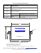
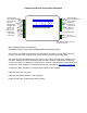
Electrical and Mechanical Specifications Physical Temp Humidity Power Data I/O Aluminum enclosure Size 3.5” x 2.75” x .75” Storage (-55°C to +150°C) Operating (-40°C to +80°C*) 95% (non-condensing) Input Output Interface Unreg Input 8 to 16VDC* @ 200ma Max +5vDC @ 100 ma Reader - Wiegand, Strobed (Clock & Data), F/2F LED - 0 to 30v * See notes on following page for temperature and power ratings 3.3” ø 0.15” 2.8” DataBender CVX-1300 1.4” Unit Height = 0.75” 3.
Initial Setup - CVX-1300 Converter The CVX-1300 will support many different input and output formats. The CVX-1300 replaces the CVX-1200 and many of the standard Cypress CVT series of converters (e.g. CVT-2232 CVT-9102). A DIP switch determines which conversion process will be used. A “Legacy” cross reference chart is provided to quickly determine which settings to use for standard Cypress converter numbers.
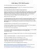
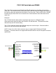
Electrical and Environmental Specifications 80 55 Ambient Temperature (Degrees Celsius) 35 -40 8 10 12 14 16 Supply Voltage Temperature/Voltage de-rating curve The CVX-1300 units should be operated with a filtered 12 Volt nominal DC supply. Any voltage between 8 and 16 volts can be utilized by following the temperature /voltage derating curve. Voltage should not exceed 16 VDC under normal operating conditions.
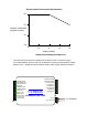
External connections and product description 1-D0/CLK Input 2-D1/Data/F2F Input 3-Aux2 LED Out 4-Ground 5-RS232 Input 6-RS232 Output 7-RLY1 N.C. 8-RLY1 Com 9-RLY1 N.O. 10-RLY2 N.C. 11-RLY2 Com 12-RLY2 N.O. 1-D0/CLK Output 2-D1/Data/F2F Output 3-Aux1 LED In 4-Analog In1 5-Analog In2 6-+5 VDC Out 7-RS485 (-) 8-RS485 (+) Converter CVX-1300 Diagnostic LED 1-Ground 2-8 to 16 VDC In Note: F2F connections support unsupervised mode Note: Terminals shown for reference.
CVX-1300 Serial data and RS485 The CVX-1300 can support both RS-232 and RS-485 signals for transmitting and receiving serial data. For most converters utilizing serial data, both interfaces are always active and may be used by making the appropriate connections to the converter. Either the RS-232 or RS-485 interface may be used, but a loss of data will occur if both interfaces have active data at the same time. Examples: The CVT-2232 function will provide a serial input and convert to a Wiegand output.
This Page left intentionally blank
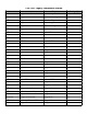
CVX-1300 Legacy Compatable formats Converter Input Output Settings(#) CVT2232 Wiegand 24 to 40 Serial 13 Digits with 1,2,3 CVT-2111 Wiegand 1 to 40 Serial Dec/Hex Digits 7, 8, 9 CVT-2110 Wiegand 1 to 48 SerialHex Digits 10 , 11, 12 CVT-2144 Wiegand 44 Serial12 Digits 13 , 14 , 15 CVT-2145 Wiegand 44/32 Serial 12/10 Digits 16 , 17 , 18 CVT-2152 Wiegand 1 to 96 Serial 24 Hex Dec 19 , 20 , 21 CVT-2151 Wiegand 1 to 40 Serial HID Hex 22 , 23 , 24 CVT-2201 Strobed/ABA Serial
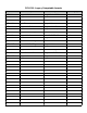
CVX-1300 Legacy Compatable formats Converter Input Output Settings(#) CVT-5201 Wiegand 26 bit 10 digit Strobed/ABA 103 CVT-2211 Wiegand ABA Serial ASCII 35,36 CVT-0126 Wiegand 26 bit Wiegand 26 bit fixed FC=215 104 CVT-9117A Serial Transcore Wiegand 26 85 CVT-3226 Wiegand 32 Bit Kastle Wiegand 26 bit Standard 105 CVT-9133 Serial ASCII Wiegand 36 bit Special 86 CVT-9501 Serial ASCII 1-12 digits F/2F 83 CVT-2485 Wiegand 24-40 Serial ASCII RS-485 1,2,3 CVT-9485 Serial ASCII
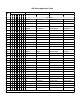
DIP Switch Application Table # 0 1 2 3 4 5 DIP SWITCH SETTING INPUT 1 2 3 4 5 6 7 8 Interface Format OUTPUT Interface Format X Wiegand 24 to 40 bits Test Mode RS-232 (9600) 13 Digits,CR X X X Wiegand 24 to 40 bits RS-232 (2400) 13 Digits,CR Wiegand 24 to 40 bits RS-232 (1200) 13 Digits,CR X X Wiegand 24 to 48 bits RS-232 (9600) 10 Digits,CR Wiegand 24 to 48 bits RS-232 (2400) 10 Digits,CR 6 7 8 9 10 11 12 13 14 15 16 17 18 19 20 21 22 23 24 25 26 27 28 29 30 X X X X X Wiegan
DIP Switch Application Table # DIP SWITCH SETTING INPUT 1 2 3 4 5 6 7 8 Interface 32 33 34 X X X X X 26 Bit X X X Wiegand ABA RS-232 (9600) ASCII Wiegand ABA RS-232 (2400) ASCII Strobed Fall ABA RS-232 (9600) 24 Hex ASCII X X X X X X X X X X X X X X X X X X X X X X X X X Wiegand 24 to 40 bits RS-232 (9600) 5 Digits, CR Radionics Readykey Wiegand 40 Bit Radionics Readykey Wiegand 34 Bit Radionics Readykey Wiegand 26 Bit TEST MODE FC = 246 BADGE = ++ X X X X X 63 X X
DIP Switch Application Table # DIP SWITCH SETTING INPUT 1 2 3 4 5 6 7 8 Interface 64 65 66 X X Format OUTPUT Interface Format X X X Strobed ABA Output TEST MODE Number = 123456789 RS-232 (9600) 10 Dec Wiegand 26 bit RS-232 (2400) 10 Dec Wiegand 26 bit X X X RS-232 (1200) 10 Dec Wiegand 26 bit RS-232 (9600) 12 Hex Wiegand Variable RS-232 (2400) 12 Hex Wiegand Variable X X X X X X X X X X X X X X X X X X X X X RS-232 (1200) 12 Hex Wiegand Variable RS-232 (9600) TransCore Wi
DIP Switch Application Table # DIP SWITCH SETTING INPUT 1 2 3 4 5 6 7 8 Interface 96 97 98 X X X X X X X X Format OUTPUT Interface Format Wiegand 24-40 bit Reserved Wiegand Wiegand 24-40 bit Wiegand 26 bit 26 bit 99 X X 100 X 101 X X X X X X X X Wiegand 35 bit Wiegand 26 bit Strobed ABA/ 12 digits Wiegand 26 bit Strobed ABA/Last 8 dig.
Standard Wiring Diagrams - CVX-1300 Converter Wiring diagrams are referenced by function and number. The specific converter descriptions will refer to these diagrams. CVX-1300 Electrical Connections 1. Serial data and RS485 2. Standard power supply connections LISTING OF STANDARD WIRING DIAGRAMS 1. Wiegand to Serial. 2. Serial to Wiegand 3. Wiegand to Wiegand 4. Strobed to Serial 5. Serial to Strobed 6. Strobed to Wiegand 7. Wiegand to Strobed 8. F/2F to Wiegand 9.Serial to F2F 10.
Wiring Diagram #1 Wiegand to Serial Reader powered by external supply (8 to 16 VDC) Data0 Data1 LED Ground Card Reader D0/Clock In D1/Data In LED Out Ground RS232 Input RS232 Output Data Bender® (-) Ground +8 to +16 VDC In Connections to Serial Device (+) DC Power Supply DB-9 Connections Direct to PC Com Port CVX Terminal DB9 Pin Ground 5 RS232 Input 3 RS232 Output 2 The Wiegand to RS232 converters support incoming commands to control the Reader LED and Converter Relay.
Wiring Diagram #1 Wiegand to Serial Reader powered by converter +5 VDC Data0 Data1 LED Ground Card Reader D0/Clock In D1/Data In LED Out Ground RS232 Input +5VDC Out RS232 Output Data Bender® (-) Ground +8 to +16 VDC In Connections to Serial Device (+) DC Power Supply DB-9 Connections Direct to PC Com Port CVX Terminal DB9 Pin Ground 5 RS232 Input 3 RS232 Output 2 The Wiegand to RS232 converters support incoming commands to control the Reader LED and Converter Relay.
Wiring Diagram #2 Serial to Wiegand Data0 Out Data1 Out Data0 Data1 Access Control Panel Ground DB9-5 DB9-2 DB9-3 Ground RS232 Input +5VDC Out RS232 Output DB9-6 Data Bender® Connections to Serial Device (-) Ground +8 to +16 VDC In (+) DC Power Supply
Wiring Diagram #3 Wiegand to Wiegand Reader powered by external supply (8 to 16 VDC) Card Reader Data0 Data1 Ground D0 Input D1 Input D0 Output D1 Output Data 0 Data 1 Ground Ground Access Control Panel Data Bender® (-) Ground +8 to +16 VDC In (+) DC Power Supply Reader powered by 5 Volt Supply Card Reader Data0 Data1 Ground D0 Input D1 Input D0 Output D1 Output Data 0 Data 1 Ground Ground Access Control Panel +5 VDC Out Data Bender® (-) Ground +8 to +16 VDC In (+) DC Power Supply
Wiring Diagram #4 Strobed to Serial Reader powered by external supply (8 to 16 VDC) Clock Strobe LED Ground D0/Clock In D1/Data In LED Out Ground RS232 Input RS232 Output Card Reader Data Bender® (-) Ground +8 to +16 VDC In Connections to Serial Device (+) DB-9 Connections Direct to PC Com Port CVX Terminal DB9 Pin Ground 5 RS232 Input 3 RS232 Output 2 The Strobed to RS232 converters support incoming commands to control the Reader LED and Converter Relay.
Wiring Diagram #4 Strobed to Serial Reader powered by converter +5 VDC Clock Strobe LED Ground D0/Clock In D1/Data In LED Out Ground RS232 Input +5VDC Out RS232 Output Card Reader Data Bender® (-) Ground +8 to +16 VDC In Connections to Serial Device (+) DB-9 Connections Direct to PC Com Port CVX Terminal DB9 Pin Ground 5 RS232 Input 3 RS232 Output 2 The Strobed to RS232 converters support incoming commands to control the Reader LED and Converter Relay.
Wiring Diagram #5 Serial to Strobed Clock Out Data Out Clock Data Access Control Panel Ground DB9-5 DB9-2 DB9-3 Ground RS232 Input +5VDC Out RS232 Output DB9-6 5 Volts (If Used) Data Bender® (-) Connections to Serial Device Ground +8 to +16 VDC In (+) DC Power Supply
Wiring Diagram #6 Strobed to Wiegand Reader powered by external supply (8 to 16 VDC) Clock Strobe LED Ground D0/Clock In D1/Data In LED Out Ground RS232 Input RS232 Output Card Reader Data 0 Data 1 Ground Access Control Panel Data Bender® (-) Ground +8 to +16 VDC In Connections to Serial Device DC Power Supply (+) Reader powered by converter +5 VDC Clock Strobe LED Ground Card Reader D0/Clock In D1/Data In LED Out Ground RS232 Input +5VDC Out RS232 Output Data 0 Data 1 Ground Access Control P
Wiring Diagram #7 Wiegand to Strobed Reader powered by external supply (8 to 16 VDC) Card Reader Data0 Data1 Ground D0/Clock In D1/Data In Clock Out Data Out Clock Data Ground Ground Access Control Panel Data Bender® (-) Ground +8 to +16 VDC In (+) DC Power Supply Reader powered by 5 Volt Supply Card Reader Data0 Data1 Ground D0/Clock In D1/Data In Clock Out Data Out Clock Data Ground Ground Access Control Panel +5VDC Out Data Bender® (-) Ground +8 to +16 VDC In (+) DC Power Supply
Wiring Diagram #8 F2F to Wiegand Reader powered by external supply (8 to 16 VDC) Card Reader F2F Ground D0 Output D1 Output F2F Input Data 0 Data 1 Ground Ground Access Control Panel Data Bender® (-) Ground +8 to +16 VDC In (+) DC Power Supply Reader powered by 5 Volt Supply Card Reader F2F Ground D0 Output D1 Output F2F Input Data 0 Data 1 Ground Ground Access Control Panel +5 VDC Out Data Bender® (-) Ground +8 to +16 VDC In (+) DC Power Supply
Wiring Diagram #9 Serial to F2F F2F Output F2F Access Control Panel Ground DB9-5 DB9-2 DB9-3 Ground RS232 Input RS232 Output +5VDC Out DB9-6 Data Bender® Connections to Serial Device (-) Ground +8 to +16 VDC In (+) DC Power Supply
Wiring Diagram #10 IButton® to Wiegand 4.
Wiring Diagram #11 Serial to Wiegand Special Application Data0 Out Data1 Out Data0 Data1 Access Control Panel Ground DB9-5 DB9-2 DB9-3 Ground RS232 Input +5VDC Out RS232 Output DB9-4 Data Bender® Connections to Serial Device (-) Ground +8 to +16 VDC In (+) DC Power Supply
Wiring Diagram #12 Radionics to Wiegand Reader powered by external supply (8 to 16 VDC) Data 0 Data 1 D0 Output D1 Output Access Control Panel Ground Data Bender® +5VDC 485(-) 485(+) Data Out (SIG) (-) Ground +8 to +16 VDC In (+) Card Reader DC Power Supply Ground (-V) +VDC (+V) 2.7 k Pullup Resistors Must be installed as shown. Resistor values between 1k and 10k should work.