CSW24V™ & CSW24VH™ VEHICULAR SWING GATE OPERATOR INSTALLATION MANUAL Your model may look different than the model illustrated in this manual. THIS PRODUCT IS TO BE INSTALLED AND SERVICED BY A TRAINED GATE SYSTEMS TECHNICIAN ONLY. Visit www.liftmaster.com to locate a professional installing dealer in your area. UL325 compliant This model is for use on vehicular passage gates ONLY and not intended for use on pedestrian passage gates.
TABLE OF CONTENTS SAFETY 1-7 PROGRAMMING Safety Symbol and Signal Word Review . . . . . . . . . . . . . . . . . . . . . . . . . . . . . . . . 1 UL325 Model Classifications . . . . . . . . . . . . . . . . . . . . . . . . . . . . . . . . . . . . . . . . . 2 Safety Installation Information. . . . . . . . . . . . . . . . . . . . . . . . . . . . . . . . . . . . . . . 3 Gate Construction Information . . . . . . . . . . . . . . . . . . . . . . . . . . . . . . . . . . . . . . .
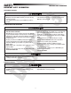
SAFETY UL325 MODEL CLASSIFICATIONS UL325 MODEL CLASSIFICATIONS I CLASS I – RESIDENTIAL VEHICULAR GATE OPERATOR A vehicular gate operator (or system) intended for use in a home of one-to four single family dwellings, or a garage or parking area associated therewith.
SAFETY SAFETY INSTALLATION INFORMATION SAFETY INSTALLATION INFORMATION 1. Vehicular gate systems provide convenience and security. Gate systems are comprised of many component parts. The gate operator is only one component. Each gate system is specifically designed for an individual application. 2. Gate operating system designers, installers and users must take into account the possible hazards associated with each individual application.
SAFETY GATE CONSTRUCTION INFORMATION GATE CONSTRUCTION INFORMATION Vehicular gates should be installed in accordance with ASTM F2200: Standard Specification for Automated Vehicular Gate Construction. For a copy, contact ASTM directly at 610-832-9585 or www.astm.org. 1. GENERAL REQUIREMENTS 1.1 Gates shall be constructed in accordance with the provisions given for the appropriate gate type listed, refer to ASTM F2200 for additional gate types.
SAFETY REQUIRED ENTRAPMENT PROTECTION DEVICES REQUIRED ENTRAPMENT PROTECTION DEVICES To prevent SERIOUS INJURY or DEATH from a moving gate: • Entrapment protection devices MUST be installed to protect anyone who may come near a moving gate. • Locate entrapment protection devices to protect in BOTH the open and close gate cycles. • Locate entrapment protection devices to protect between moving gate and RIGID objects, such as posts or walls.
SAFETY IMPORTANT SAFETY INFORMATION IMPORTANT SAFETY INFORMATION INSTALLATION To prevent SERIOUS INJURY or DEATH from a moving gate: • Pinch points must be guarded at all times. Install enclosed-style gate tracks and roller guards. • Place screen mesh 4 feet (1.2 m) high on the gate to prevent access through openings anywhere the gate may travel. • Mount controls at least 6 feet (1.8 m) from the gate or ANY moving part of the gate. • Install Warning signs on EACH side of gate in PLAIN VIEW.
SAFETY IMPORTANT SAFETY INFORMATION IMPORTANT SAFETY INFORMATION ADDITIONAL FEATURES To prevent SERIOUS INJURY or DEATH from a moving gate: • Entrapment protection devices MUST be installed to protect anyone who may come near a moving gate. • Locate entrapment protection devices to protect in BOTH the open and close gate cycles. • Locate entrapment protection devices to protect between moving gate and RIGID objects, such as posts or walls.
INTRODUCTION OPERATOR SPECIFICATIONS + CARTON INVENTORY & OPERATOR DIMENSIONS OPERATOR SPECIFICATIONS This model is intended for use in vehicular swing gate applications: Gate Classifications: CLASS I, II, III, & IV Main AC Supply: 120 Vac or 240 Vac Solar Power Max: 24 Vdc at 50 watts max.
INTRODUCTION FEATURES FEATURES OPERATOR FEATURES • Advanced “Centerpiece” Control Board • EMI AC Power Surge Protection and Filter Board - Main AC voltage input selection: 120 Vac (factory setting) or 240 Vac (field change) • DC motor with extended brush life • AC powered with integrated Evercharge battery backup and management • 24 Vdc accessory power • Programmable with up to 50 remote controls and 2 keyless entries. Compatible with MyQ™ devices and Security✚ 2.
PREPARATION SITE PREPARATION Check the national and local building codes BEFORE installation. GATE CONDUIT & CONCRETE PAD Gate must be constructed and installed according to ASTM F2200 standards (refer to page 4). Gate must fit specifications of operator (refer to specifications). Conduit must be UL approved for low and high voltage. Consider the operator placement BEFORE installing the pad or post.
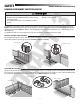
SITE PREPARATION SAFETY SAFETY Entrapment protection devices are required to protect against any entrapment or safety conditions encountered in your gate application (refer to page 5 for more details). Install warning signs on both sides of the gate. STANDARD INSTALLATION (Inside Property) ! The illustration is an example of a standard installation.
INSTALLATION STANDARD INSTALLATION ONLY STANDARD INSTALLATION ONLY CONDUIT LOCATION For compact installation start on page 14. 5.5” DETERMINE LOCATION FOR CONCRETE PAD AND OPERATOR 4.5” 3 1” 13.6” 6.5” 4” DO NOT run the operator until instructed. Below is a recommended guide for positioning the concrete pad: 1 2 12.2” (Conduit) 1.5” 3” 2.49” 20” Subtract 14 inches from A to get B, the distance from the center of the output shaft to the center of the gate hinge. 15” Open the gate 90°.
INSTALLATION STANDARD INSTALLATION ONLY STANDARD INSTALLATION ONLY POSITION THE GATE BRACKET NOTE: It may be necessary to attach horizontal reinforcement to the gate before attaching the gate bracket. 1 2 3 Position the operator arm onto the output shaft so that the pin slides into the slot. Measure 1/4 the length of the gate from the hinge center. Make sure the operator arm is level and tack weld the gate bracket in this position.
INSTALLATION COMPACT INSTALLATION ONLY COMPACT INSTALLATION ONLY DETERMINE LOCATION FOR CONCRETE PAD AND OPERATOR TOP VIEW OF OPERATOR AND GATE Gate Hinge Center DO NOT run the operator until instructed. Refer to the illustration to determine the measurements and location of the concrete pad. NOTE: When lifting the operator use the handle to avoid damaging the operator.
INSTALLATION COMPACT INSTALLATION ONLY COMPACT INSTALLATION ONLY SHORTEN THE OPERATOR ARM For a compact installation the operator arm will have to be shortened. 1 2 3 1 Take the operator arm apart and remove the inner sleeves from the outer tubing. Cut the outer tubing of the operator arm sections to the lengths shown. Put the arm back together and adjust the arm to the measurements as shown. Use the set screws on the arm to temporarily hold the arm in place while determining the correct measurements.
INSTALLATION INSTALLATION CONTINUED... INSTALLATION CONTINUED... WELD THE OPERATOR ARM 1 Once the operator arm measurements are verified: 1 2 3 4 3 Weld the gate bracket to the gate. Weld the short arm section. Weld the long arm section. Remove the set screws from the arm. NOTE: Completely weld around the outer tubing and bracket.
WIRING WIRE THE ENTRAPMENT PROTECTION DEVICES + EARTH GROUND ROD WIRE THE ENTRAPMENT PROTECTION DEVICES Entrapment protection devices are required. Refer to page 5 for more information regarding application. To prevent SERIOUS INJURY or DEATH from a moving gate: • Entrapment protection devices MUST be installed to protect anyone who may come near a moving gate. • Locate entrapment protection devices to protect in BOTH the open and close gate cycles.
WIRING POWER WIRING POWER WIRING NUMBER OF CYCLES PER DAY This operator can be wired for either 120 Vac or 240 Vac or a solar panel (not provided). Follow the directions according to your application. For dual gate applications, power will have to be connected to each operator. Main power supply and control wiring MUST be run in separate conduits.
WIRING POWER WIRING POWER WIRING CONTINUED... 120 VAC AND 240 VAC 1 2 3 4 5 6 7 Turn off the AC power from the main power source circuit breaker. Run the AC power wires to the operator. Remove the junction box cover. Connect the green wire to the earth ground rod and AC ground using a wire nut. NOTE: The earth ground rod can be grounded to the chassis. Connect the white wire to NEUTRAL using a wire nut. Junction Box Cover Connect the black wire to HOT using a wire nut. Replace the junction box cover.
WIRING DUAL GATES ONLY DUAL GATES ONLY There are two options for dual gate communication: wired or wireless. Follow the directions according to your application. Do not use wired and wireless communication simultaneously. Wired dual gate applications will have a longer battery standby time than wireless applications. WIRED DUAL GATES Before digging, contact local underground utility locating companies. Use PVC conduit to prevent damage to cables.
WIRING DUAL GATES ONLY DUAL GATES ONLY WIRELESS DUAL GATES Turn on power to the operator. TO ACTIVATE THE WIRELESS FEATURE: 1 Choose an operator to be the network primary operator. All wireless accessories will need to be programmed to the primary operator. 2 Press and release the LEARN RADIO button on the primary operator. The green XMITTER LED will light. 3 Press and release the LEARN RADIO button again on the primary operator. The NETWORK LED will light.
WIRING DUAL GATES ONLY + CONNECT BATTERIES DUAL GATES ONLY BIPART DELAY/SYNCHRONIZED CLOSE The LOCK/BIPART DELAY switch is used only with dual gate applications and serves two functions: • BIPART DELAY SWING GATE APPLICATIONS: The BIPART DELAY is used in applications where a mag-lock, solenoid lock, or decorative overlay would require one gate to close before the other.
WIRING CONNECT BATTERIES CONNECT BATTERIES 33AH BATTERIES The batteries are charged in the circuit by the integrated transformer. The batteries are for battery backup or solar installation. The 33AH application requires the 33AH battery harness (Model K94-36596) and an additional battery tray (Model K1036183) to allow more space in the enclosure. The heater option cannot be used with the 33AH battery application. Remove the outlet housing from the chassis by removing the screws (2).
ADJUSTMENT LIMIT AND FORCE ADJUSTMENT LIMIT AND FORCE ADJUSTMENT To reduce the risk of SEVERE INJURY or DEATH: • Without a properly installed safety reversal system, persons (particularly small children) could be SERIOUSLY INJURED or KILLED by a moving gate. • Too much force on gate will interfere with proper operation of safety reversal system. • NEVER increase force beyond minimum amount required to move gate. • NEVER use force adjustments to compensate for a binding or sticking gate.
ADJUSTMENT LIMIT AND FORCE ADJUSTMENT + OBSTRUCTION TEST FINE TUNE THE FORCE 1 The FORCE DIAL on the control board is used for fine tuning the force in cases where wind or environmental changes may affect the gate travel. Based on the length and weight of the gate it may be necessary to make additional force adjustments. The force setting should be high enough that the gate will not reverse by itself nor cause nuisance interruptions, but low enough to prevent serious injury to a person.
PROGRAMMING REMOTE CONTROLS + ERASE ALL CODES REMOTE CONTROLS A total of 50 Security✚ 2.0™ remote controls and 2 keyless entries (1 PIN for each keyless entry) can be programmed to the operator. NOTE: When the memory is full the operator will exit programming mode and the remote control/keyless entry will not be programmed. The memory will need to be erased before programming any additional remote controls/keyless entries.
FINISH INSTALLATION INSTALL THE COVER INSTALL THE COVER The operator cover consists of two pieces: a rear cover and a front cover. The front cover can easily be removed to access the electrical box. To access the reset switch slide the access door up. The front cover and access door can be locked with the key. TO INSTALL THE COVER 1 2 Remove the operator arm from the output shaft by releasing the handle.
OPERATION MANUAL DISCONNECT + RESET SWITCH + REMOTE CONTROL + HEATER (IF APPLICABLE) MANUAL DISCONNECT Manual Disconnect Handle Press the reset switch to RESET/DISCONNECT. Release the handle on the operator arm to allow the gate to be opened and closed manually. On a dual gate application the handle must be released on both operators. To resume normal function tighten the handle by pushing it down.
ADDITIONAL FEATURES GATE OPERATOR SETUP EXAMPLES GATE OPERATOR SETUP EXAMPLES The following are example setups for the gate operator. Your specific site requirements may be different. Always setup the operator system to the site requirements, including all necessary secondary entrapment protection systems.
ADDITIONAL FEATURES CONTROL BOARD OVERVIEW CONTROL BOARD OVERVIEW SET OPEN Button The SET OPEN button sets the OPEN limit. See Adjust Limits section. SET CLOSE Button The SET CLOSE button sets the CLOSE limit. See Adjust Limits section. MOVE GATE Button The MOVE GATE buttons will either open or close the gate when the operator is in Limit setting mode. See Adjust Limits section. BIPART DELAY Switch The LOCK/BIPART DELAY switch is used only for dual gates. See Bipart Delay section.
ADDITIONAL FEATURES ACCESSORY FEATURES ON CONTROL BOARD ACCESSORY FEATURES ON CONTROL BOARD A Open Input (& common) (3-Button Control Station, 4 terminals total) Open command - opens a closed gate. Hard open (maintained switch overrides external safeties and resets alarm condition) If maintained, pauses Timer-to-Close at OPEN limit. Opens a closing gate and holds open an open gate (within line-of-sight).
ADDITIONAL FEATURES EXPANSION BOARD OVERVIEW EXPANSION BOARD OVERVIEW To AVOID damaging the circuit board, relays or accessories, DO NOT connect more than 42 Vdc (32 Vac) to the AUX relay contact terminal blocks. QUICK CLOSE Switch OFF: No change to the gate's normal operation. ON: When CLOSE EYES/Interrupt loop is deactivated it causes an opening or a stopped gate to close (ignores the Timer-to-Close).
ADDITIONAL FEATURES ACCESSORY FEATURES ON EXPANSION BOARD ACCESSORY FEATURES ON EXPANSION BOARD A Open Input (& common) (3-Button Control Station, 4 terminals total) Open command - opens a closed gate. Soft close (maintained switch does not override external safeties and does not reset alarm condition) If maintained, pauses Timer-to-Close at OPEN limit. Opens a closing gate and holds open an open gate.
ADDITIONAL FEATURES LIMIT SETUP WITH A REMOTE CONTROL LIMIT SETUP WITH A REMOTE CONTROL To set the limits using a remote control, first you will need a 3-button remote control that has been programmed for OPEN, CLOSE, and STOP. Refer to the Programming section. To reduce the risk of injury keep clear of moving arm while setting limits. INITIAL LIMITS AND FORCE ADJUSTMENT For dual gate applications the limits will have to be set for each operator.
MAINTENANCE MAINTENANCE CHART + BATTERIES MAINTENANCE CHART Disconnect all power (AC, solar, battery) to the operator before servicing. The operator's AC Power switch ONLY turns off AC power to the control board and DOES NOT turn off battery power. ALWAYS disconnect the batteries to service the operator.
TROUBLESHOOTING CONTROL BOARD LEDS CONTROL BOARD LEDS The control board is equipped with many LEDs that have a variety of functions. The control board LEDs indicate the status of the operator, assist with programming, and diagnose potential problems with the operator. LIMIT SETUP LEDS GREEN XMITTER LED DIAGNOSTIC CODES LEDS STATUS LEDS INPUT LEDS RESET LIMIT SETUP LEDS SET OPEN LED SET CLOSE LED OPERATOR MODE EXPLANATION BLINKING BLINKING NORMAL MODE Limits are not set.
TROUBLESHOOTING CONTROL BOARD LEDS CONTROL BOARD LEDS DIAGNOSTIC CODES LEDS YELLOW DIAGNOSTIC LED RED DIAGNOSTIC LED # BLINKS MEANING CORRECTION # BLINKS MEANING CORRECTION 1 BLINK Low Power Mode (not an error) 2 BLINKS Current Sense 2 BLINKS ID resistor failure Check ID resistor wiring, clear limit settings and reset limits Motor control circuit fault, replace control board 3 BLINKS FET Failure 3 BLINKS Exceeded Maximum Run Timer Check gate travel, if necessary adjust force setting
TROUBLESHOOTING TROUBLESHOOTING CHART FAULT POSSIBLE CAUSES CORRECTIONS Operator does not run and diagnostic LED not on. a) b) c) d) No power to control board Open fuse If on battery power only, low or dead batteries Defective control board a) b) c) d) Check AC and battery power Check fuses Charge batteries by AC or solar power or replace batteries Replace defective control board Control board powers up, but motor does not run.
TROUBLESHOOTING TROUBLESHOOTING CHART FAULT POSSIBLE CAUSES CORRECTIONS Gate stops during travel and reverses immediately. a) Check DIAGNOSTIC LEDs b) Inherent force obstruction detection c) External Entrapment Protection Device activation d) Control (Open, Close) becoming active e) Vehicle loop detector active f) Low battery voltage a) Use Diagnostic code to identify issue b) Check for obstruction in gate’s path or travel. Disconnect arm from gate and move gate manually.
TROUBLESHOOTING TROUBLESHOOTING CHART FAULT POSSIBLE CAUSES CORRECTIONS Obstruction in gates path does not cause gate to stop and reverse a) Force setting too high a) Adjust force setting. Retest that obstruction in gate’s path causes gate to stop and reverse direction. Photoelectric sensor does not stop or reverse gate. a) Incorrect photoelectric sensor wiring b) Defective photoelectric sensor a) Check photoelectric sensor wiring.
TROUBLESHOOTING TROUBLESHOOTING CHART FAULT POSSIBLE CAUSES CORRECTIONS Accessories connected to Accessory power not working correctly, turning off, or resetting. a) Accessory power protector active b) Defective control board a) Disconnect all accessory powered devices and measure accessory power voltage (should be 23 – 30 Vdc). If voltage is correct, connect accessories one at a time, measuring accessory voltage after every new connection.
42 Black White Black Red EMI FILTER/SURGE PROTECTION BOARD Transformer 375 VA, 24V, 120V - - Bridge Rectifier Orange Orange NOTE: The accessory outlet is disabled and cannot be used with the 240 Vac option. Purple Brown Blue + - Red Gray Black N Black Red RESET Ferrite EMI Filters Red Wire Loop N.C. Field Wiring Photoelectric Sensors Photoelectric Sensors Blue Yellow N.C. Ground the shield of the cable to the chassis ground of each operator.
ACCESSORIES ENTRAPMENT PROTECTION DEVICES MISCELLANEOUS PHOTOELECTRIC SENSORS (NON-CONTACT) HEATER The photoelectric sensors are designed to detect an obstacle in the path of the electronic beam and stop the operator. Includes mounting brackets. Models AOMRON E3K-R10K4-NR (retro-reflective), RETROAB 60-2728 (retro-reflective), CPS-UN4 (through beam) Keeps operator, gearbox and batteries at suitable temperature when outside temperature is below 0°F for extended periods of time.
REPAIR PARTS INDIVIDUAL PARTS ITEM 1 2 PART NUMBER K13-36117 K77-36538 3 4 5 6 7 K73-36109 K76-34644 K19-50038 K32-35814 K15-50B18LKGH 8 K77-36539 9 10 11 12 13 K32-34655-1 K10-36395 29-NP712 K204C0211 K1A6408 14 15 16 17 K52C0481 K1D6597-1CC K1D6686CC K76-34728 18 19 20 21 22 23 24 25 26 K77-36541 K76-36398 K77-36542 K180A0357 K94-35152 K75-36260 Q118 K13-34729 Q061 27 28 29 Q059 Q060 Q104 DESCRIPTION Cludge Cover Operator Cover with labels, keys, and lock assembly Chassis APS Encoder with ca
REPAIR PARTS 1 26 28 27 9 8 29 12 22 10 7 11 6 20 5 3 4 19 13 14 21 15 17 16 2 23 24 45 25 18
WARRANTY 7 YEAR RESIDENTIAL / 5 YEAR COMMERCIAL CSW24V™ AND CSW24VH™ LIMITED WARRANTY The Chamberlain Group, Inc.