
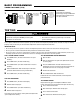
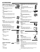
Owner's manual

© 2011, The Chamberlain Group, Inc.
01-34213E All Rights Reserved
IMPORTANT NOTES:
1. The 3-Button Control Station provided must be connected for operation.
2. If a STOP button is not used, a jumper must be placed between terminals 3 and 5.
3. If INTERLOCK is not used a jumper must be placed between terminals 3 and 4.
4. When adding accessories, install them one at a time and test each one after it is added to ensure proper installation and operatio
n
with the Commercial Door Operator.
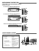
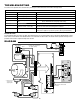
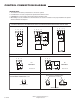
3 BUTTON STATION OR 3 POSITION KEYSWITCH WITH SPRING RETURN TO CENTER AND STOP BUTTON
2 OR MORE KEY LOCKOUT
7 6 3 5
Stop
Close
Open
Stop
Close
Open
7 6 3 5
Stop
Close
Open
2 BUTTON STATION OR 3 POSITION KEYSWITCH WITH SPRING RETURN TO CENTER
STANDARD
7 6 3
Close
Open
C2
MODE ONLY
2 OR MORE
7 6 3
Close
Open
Close
Open
C2
MODE ONLY
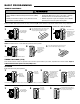
DEVICE TO REVERSE
EXTERNAL INTERLOCK
1
2
3
4
3
4
Remove Factory Installed Jumper
When Interlock is Used
ONE 2 OR MORE
STANDARD
7 6 3 5
Stop
Close
Open
All Wiring Types
Keyswitch
Sensing Device
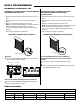
Note: For photoelectric sensors connection options see
ENTRAPMENT PROTECTION section.
See note 2.
See note 2.
CONTROL CONNECTION DIAGRAM