
Owner's manual

25
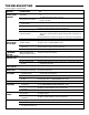
CONDITION POSSIBLE CAUSE FIX
OPERATOR WILL NOT
RESPOND TO ANY
COMMANDS
A) No power
➤ Verify primary line voltage (120 Vac, 60 Hz) is present at terminals L1 &
L2.
The LED will fl ash when power is present.
B) Stop circuit not complete
➤ Verify Stop Button input (terminals 3 & 5) is properly wired and stop
button is not stuck.
C) Stuck button on 3-button
control station
➤ Verify that all buttons are actuating freely and releasing properly.
D) Interlock input activated
➤ Verify jumper is located at terminals 3 & 4 if interlock is not present.
➤ Verify interlock is properly wired and not activated.
E) Motor overload tripped
➤ Overload is internal within motor. Allow to cool and retry.
F) Accessory failure
➤ Attempt to close by holding the CLOSE button for more than 5 seconds. If
door closes, check accessory for proper wiring, polarity, connections or
damage.
➤ Verify photoelectric sensors are aligned or sensing edge is not activated.
G) Possible component failure
➤ Call Technical Support for assistance.
OPERATOR MAKES
NOISE BUT DOOR
DOES NOT MOVE
A) Clutch slipping
➤ Adjust clutch, see ADJUSTMENT section.
B) Brake not releasing
(if present)
➤ Verify brake assembly operation and wiring.
C) Door operation problem
➤ Disconnect trolley and check door for proper operation.
OPERATOR MOVES
IN THE WRONG
DIRECTION
OPEN and CLOSE button
wiring connection reversed
➤ Check 3-button control wiring.
DOOR DRIFTS AFTER
OPERATOR STOPS
A) Door not balanced properly
➤ Disconnect trolley assembly and check door for proper operation.
B) Clutch slipping
➤ Adjust clutch, see ADJUSTMENT section.
C) Brake not functioning
properly
➤ Check brake mechanism to ensure brake lever is free and brake pads are
engaging the brake disc.
DOOR OPENS/
CLOSES TOO FAR
Limits not adjusted properly
➤ Adjust limits. See ADJUSTMENT section.
DOOR REVERSES
UNEXPECTEDLY
Intermittent Entrapment
Protection Device activation
➤ Check all connections.
TTC NOT
FUNCTIONING
A) Monitored Entrapment
Protection Devices
➤ Check all connections. Verify photoelectric sensors are not blocked and the
sensing edge is not activated.
B) TTC temporarily disabled
➤ Close and Open the door. TTC will be re-enabled.
C) TTC not programmed
properly
➤ Reprogram TTC. See PROGRAMMING TTC section.
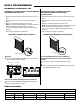
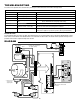
RADIO FUNCTIONALITY NOTE: Built in radio receiver compatible with all LiftMaster 315 MHz remote control devices.
NO RESPONSE
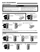
A) Remote control is not
programmed
➤ See PROGRAMMING REMOTE CONTROLS section.
B) Remote control not
compatible
➤ Obtain qualifi ed LiftMaster remote control device.
C) Low battery
➤ Replace battery.
REMOTE CANNOT BE
LEARNED
A) Low battery
➤ Replace battery.
B) Remote control not
compatible
➤ Obtain qualifi ed LiftMaster remote control device.
POOR RADIO RANGE
A) Low battery in remote
➤ Replace battery.
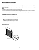
B) Antenna not confi gured
➤ See SETUP RADIO ANTENNA.
C) Ambient radio interference
or building structural issue
➤ Use EXTERNAL ANTENNA kit (see ACCESSORIES page).
Technical Support 1-800-528-2806
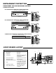
TROUBLESHOOTING