
Manual


BGU • BGU-D Barrier Gate Operator Installation Guide - 22 - P558 Revision X13 8-11-2011
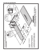
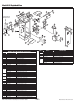
Model BGU Exploded View
ARM SHOWN FOR
REFERENCE ONLY
9
46
70
47
30
30
30
2
1
29
47
30
6
11
42
40
40
42
38
30
47
6
11
29
33
43
44
63
64
19
21
28
7
33
59
56
55
12
26
56
55
23
59
72
73
71
74
50
24
17
63
64
62
54
53
5
52
3
80
77
MODEL BGU MECHANICAL PARTS LIST
REF. # PART # DESCRIPTION
1 2110-839 Enclosure only (without Door)
2 2100-2142 Removable Enclosure Top
3 2110-318* Louvered Door Assembly with Lock
2100-2141 Latch for Enclosure Top
* Specify color and texture
5 2220-008 Lock Assembly with Keys
6 2110-746 Bearing Block Assembly Kit
7 2110-170 Drive Shaft Assembly
8 2110-732 Gate Arm Flange
9 2100-1886 Arm Attachment Channel
11 2200-898 Bearing only
12 2110-441 Connecting Link with Bearings
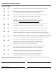
17
MOTORS
2500-2108 A.O. Smith 1/3 HP 115V 1 PH
2500-2252 Emerson 1/3 HP 115V 1 PH
2500-2308 1/2 HP 208/230 VAC, 1 PH
19
GEAR REDUCERS 60:1
2200-758 MMTC
2200-667 Canimex
21
2200-118 Reducer Pulley, 4” (10’ Arm)
2100-388 Reducer Pulley, 5” (12’ Arm)
23
2200-208 V-Belt, 26” (10’ Arm)
2200-234 V-Belt, 28” (12’ Arm)
24 2200-235 Motor Pulley, 1-5/8”
26 2200-136 Bearing only
28 2400-285 Key, 3/16” x 3/16” x 1-7/8”
29 2400-178 Carriage Bolt, 3/8”-16 x 1-1/2”
33 2200-314 Set Collar, 1-1/4”
34 2400-474 Spring Pin, 0.37” x 2”
38 2500-764 Limit Switch
43 2300-028 Limit Cam
50 2400-238 Key, 3/16” x 3/16” x 1-1/4”
55 2400-188 Thrust Washer
56 2400-165 Shoulder Bolt, 1/2”-13 x 2”
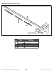
70 2100-1670 Arm Flange Bracket with Cutting Edge
71 2100-1804 Rear Accessory Shelf
72 2100-1799 Power Disconnect Box Mounting Bracket
REF. # PART # DESCRIPTION
73
2510-422 115 VAC Power Box Assembly
2510-430 230 VAC Power Box Assembly
74 2100-1820 Front Accessory Shelf
2520-523 Wiring Harness Assembly (not shown)
77 2100-2143 Power Box Mounting Strap
80
2500-2393 APeX Module
2100-2104 APeX Mounting Plate
2300-1025 Plastic Cover Only
2510-423 Knob Kit
2400-343 1/4-20 Tinnerman Clip