
User Manual


18
PHOTO
Beam
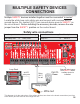
MULTIPLE SAFETY DEVICES
CONNECTIONS
Multiple devices installed together must be connected .
. efore installing the accessory devices, remove the wire
jumper from the position
in seriesSAFETY “ ”
SAFETY
SAFETY
Locate the white loop rack safety wire and connect with common wire of
second device. Dry contact (N.C.) from second device goes to on
the circuit board B
on the control board.
From Second Accessory To Board pin
Relay N.C. To SAFETY
From Loop rack to Second Accessory
White safety wire To Relay COM
This diagram is for the relay wires of the safety devices, two wires to the board connections (one from
each device) and two wires to the orange wire nut.
Wire nut
Safety wire connections
Remove jumper
from when
a safety device is
installed.
wire
SAFETY
Relay (COM)
Relay
(N.C.)
AB
C8RB
LMC64
82AIM
1002
1002
1002
1002
1002
1002
1002
1002
1002
1002
1
0
0
2
1002
1002
1
0
0
2
121
2
2402
3002
6040
1001
1001
1001
1501
1501
1501
1501
1501
1501
1501
1501
1501
1501
150
1
1501
1501
150
1
MAAF
S21B
33
HFK
5GN
802
360G
B
O
N
DR127-330
43CL07 E
U
V
V
safety wire
Exit Loop
Phantom Loop
Safety Loop
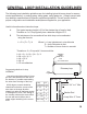
See side for
Jumper setting
Loop C
onnections
Exit
Loop
Loop
Loop
Safety
Phantom
24VAC/
12VDC
Ground
Exit
Phantom
Safety
Loop Rack
WHITE