® ® US L I STED Pending UL325 compliant WWW.ALLOMATIC.NET UL991 compliant SW-350DC & SW-300DC Installation Manual Copyright © 2008 all-o-matic inc. www.allomatic.
TABLE OF CONTENTS Important safety instructions........................................................ 2&3 Different UL 325 class types............................................................. 4 Concrete pad Specs for SW-300DC................................................. 5 Concrete pad Specs for SW-350DC................................................. 6 Concrete Operator & Arm Layout.............................................. 7,8&9 Compact Installation..........................................
IMPORTANT SAFETY INSTRUCTIONS WARNING To reduce the risk of injury: READ THE FOLLOWING DIRECTIONS. DO NOT EVEN THINK OF STARTING UNTIL YOU HAVE READ AND UNDERSTAND THESE DIRECTIONS. IF THERE IS SOMETHING YOU DO NOT UNDERSTAND CALL US. Never let children operate or play with gate controls. Keep the remote control away from children. Always keep people and objects away from the gate. No one should cross the path of the moving gate. This operator must be tested monthly.
INSTALL THE GATE OPERATOR ONLY WHEN YOU HAVE READ THE FOLLOWING: *Confirm that the gate operator being installed is appropriate for the application. *Confirm that the gate is designed and built according to current published industry standards. *Confirm that all appropriate safety features and safety accessory devices are being incorporated, including both primary and secondary entrapment protection devices. *Make sure that the gate works freely before installing the operator.
DIFFERENT UL 325 CLASS TYPES Class one: Residential A vehicle gate operator intended for use at a home of one to four single family dwellings, garages or parking area. Class Two: Commercial or General Public Access A vehicular gate operator intended for use at a commercial location or building such as a multi-family housing unit (five or more single family units), hotel, garages, retail stores, other buildings servicing the general public.
CONCRETE PAD FOR SW-300DC Four red head Bolts / ”X 3 / ” 1 Operator plastic Cover 2 1 2 24” 13.5” Area for Conduit(s) Operator Concrete Pad Operator frame 9.5” 24” 23” 25.
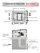
CONCRETE PAD FOR SW-350DC 25 1/2” Operator plastic cover 15” Four red head Bolts 1/2” X 31/2” 24” 9” Area for Conduit(s) Operator concrete pad Operator frame 211/2” 30” 141/2” When possible install 4” above ground 17 1/4 ” 4” Low voltage single conduit for Master/Slave 24” Footing for gate operator High voltage conduit 6
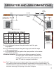
OPERATOR AND ARM DIMENTIONS HINGE CENTER This distance is from the gate in open position to edge of the pad. Refer to note. 2” A OUTSIDE POST INSIDE B C Refer to note below. SE CO ND AR Y PR IM AR Y CONCRETE PAD Dimentions Chart Gate length Less than 12” A B C Minimum Distance 36” 35” 14” 34” 13’-15’ 42” 41” 14” 37” 16’-22’’ 48” 47” 14” 40” Minimum distance A: Is the distance between the gate bracket and the gate hinge point.
OPERATOR AND ARM LAYOUT Hinge point “A” Out In Point Y X Bracket Mark ground under gate bracket with gate closed. This will be point Y 1 Bracket Point Z X Mark ground under gate bracket with gate open. This will be point Z 14” Bracket Hinge point Out In X Point Y Bracket Point Z X Draw a line from point Y past the point Z as shown. This should be laid on the ground. The operators center shaft goes on this line.
ARM LAYOUT & OPERATOR PLACEMENT CONTINUED Bracket Hinge point Point Y X 3 Bracket Point Z X Measure distance from the point Y And point Z. Say distance is 60”, divide this number by 2,which =30”. This is the length of primary arm in next drawing. PLEASE BE EXACT!!! Center shaft of Operator This ARM section is half the distance between point Y and point Z as shown above. IT MUST BE EXACT!!! This pipe does not need to be measured after primary arm is installed this pipe makes up the balance of arm.
SWINGER COMPACT INSTALLATON To use this installation the gate must be 12’ or less. HINGE CENTER 27” OUTSIDE INSIDE 8” 35” SE CO ND AR Y 20” Use these measurements, only if the distance between the wall and the gate in the open position is 20” to 34”. If you have more than 34” refer to standard installation.
TORQUE LIMITER AND ARM The torque limiter is shipped loose (not adjusted). You must use a 20” pipe wrench to adjust the large torque limiter nut on the operator as shown in the images below. Tighten torque limiter nut until arm does not slip when the operator is running. Also run gate and grab gate at mid cycle to make sure torque limiter will slip. This is an important adjustment, so please take your time and do it right. Torque limiter adjusting nut.
GATE TRAVEL ADJUSTMENT Locate limit switch. Step 1: Turn the power off on operator. Step 2: Use an allen wrench to loosen up the limit cams. Turn the limit Cams to desired direction. Step 3: tighten the allen screw. Step 4: Turn the operator back on. Step 5: Run gate operator. If more adjustment is needed, repeat the steps.
OPENING DIRECTION SETTINGS Use OPEN L/R dipswitch to change the opening direction on the operator. OFF for left hand opening, ON for right hand opening. .01 I / 5W O O I0615 20M 1001 1001 6040 1212 2402 3002 MAAF S21B C8RB LMC64 82AIM 33 HFK 5GN F260 1001 UC3906DW U 74ZF2CW 602 SS26 602 SS26 1212 DR127-330 43CL07 E 1131 9531 ON 802 B 360G 4750 602 SS26 829B R616 802 B 360G ON SS 14 911C0 107A 100 HFK. 7J2 2491 683 Coilcraft V 710 KE.
ELECTRICAL CONNECTION OPERATORS MUST BE PROPERLY GROUNDED! 230V Power switch 115V NOTE: When applying 230V to operator make sure voltage switch is flipped to 230V position. GRD LINE 1 LINE 2 120 Volt Electrical Plug. Power connection = LINE 1 LINE 2 = | 115VAC 115V N | 220VAC Single Phase 220V LINE 1 115V HOT 220V LINE 2 GND Connect to ground. Use a proper ground rod for a ground reference. Use the shortest and thickest wire possible for ground.
SWINGER LOOP LAYOUT Outside Safety loop WIRED IN SERIES 5 FT 5 FT 5 FT Center Phantom loop 5 FT Gate in open position Inside Safety loop 1 1/2 IN 5 FT TWISTED 6 TURNS PER FOOT 1/4 IN 5 FT Exit loop WHEN USED This is a normal loop layout. Remember when connecting to an All-OMatic circuit board you use the normally closed contacts from your safety loop detector and normally open contacts from the exit loop.
GENERAL LOOP INSTALLATION GUIDELINES The following loop installation guidelines are for installing typical driveway loops for access control applications (i.e. parking gates, sliding gates, swing gates etc...) Always consult with loop detector manufacturers for specific equipment guidelines. This will confirm that the proper configuration and installation techniques are applied for your application. Useful information about inductive loops: A.
ACCESSORY CONNECTIONS The circuit board 12 or 24VDC output provides up to 500 mAmps of power for accessories. More than two or three accessories will require a separate power supply. NOTE: 12 or 24VDC Accessories only.
MULTIPLE SAFETY DEVICES CONNECTIONS Multiple SAFETY devices installed together must be connected “in series”. Locate the white loop rack safety wire and connect with common wire of second device. Dry contact (N.C.) from second device goes to SAFETY on the circuit board. Before installing the accessory devices, remove the wire jumper from the SAFETY position on the control board.
® LPR-1 LOOP RACK INATALLATION This is a typical loop configuration for a gated driveway. Remember when connecting to an All-O-Matic circuit board the safety (reverse) uses normally closed contacts from the loop detector, the wire jumper from the safety connector needs to be removed when a safety loop is inatalled. You must twist your wires from your exit point of the saw cut all the way to the loop detectors, no exceptions.
LEADING EDGE CONNECTION 1002 1002 1002 1002 1002 1002 2402 1001 1001 6040 1001 ON 1501 1501 1501 1501 1501 1501 1501 1501 1501 1501 1501 1501 MAAF S21B 1002 802 B 360G 1002 1002 C8RB LMC64 82AIM 1002 1212 3002 1002 33 HFK 5GN 1501 1501 V U V 1002 DR127-330 43CL07 E RED wire to 12VDC BLACK wire to COMMON LEADING EDGE SENSOR Wireless edge Receiver Connect one of the wires from leading edge and/or one of the grey wires from a wireless edge receiver to COMMON connector on c
THREE BUTTON STATION SYSTEM See push button connections below. C8RB LMC64 BO U RNS 1001 1 PHILIPS 1001 RNS BO U ON 802 B 360G 8 33 6 3 1001 1001 RNS 2491 BO U C8RB LMC64 82AIM 2262 1 8 33 6 3 100 HFK. 7J2 476E 476E 900R3 911C0 9 1AM 900R3 107A W107DIP - 3 MAGNECRAFT PHILIPS 104 Coilcraft F 3 710 KE. 8 33 6 1002 710 KE. 1 1210 1001 C8RB LMC64 82AIM 802 B 360G 72CB74K G4 Ls14 58ADC1K G4 Ls07 72CB74K G4 Ls14 58ADC1K G4 Ls07 4021 ON F 710 KE.
MAGNETIC/SOLENOID LOCK CONNECTIONS Magnetic lock installation requires a step down transformer with appropriate voltage for the specific lock accessory. Operator will provide a 120VAC outlet for the step down transformer. Connections: Plug the lock device transformer to the 120VAC outlet plug.
MASTER/SLAVE CONNECTION Before connecting master/slave gate operators together, test and adjust the limit switches and the ERDs for each operator as “stand alone” machines. All accessories must be installed on the master board, no exception. See page 27 for dip switch settings. Use a two wire shielded cable and run it through a UL listed conduit for master/slave connection. Follow the wiring diagram as shown below. Master Board Slave Board +.....................Positive to Positive...................+ -..
RADIO RECEIVER CONNECTIONS 4 wire receiver: connect the two relay wires to 1 & 2 terminals. Black negative wire to terminal 1 and Red positive wire to terminal 3 on receiver strip outside control box as shown below. 1AM 9 1001 829B R616 829B R616 0618 IOR 0618 IOR 0618 829B R616 145 710 KE.
OPEN AND CLOSE ELECTRONIC REVERSING SENSOR(ERDs) ADJUSTMENT Open and Close ERD SENSITIVITY .
TIMER ADJUSTMENT TIMER ON: Timer to close, can be set from 1 to 60 seconds. TIMER OFF: Gate operation is push button to open, push button to close. TO OVERRIDE THE TIMER: Turn the RADIO switch to the “ON” position. This will allow the radio receiver to close the gate before the timer. TIMER ADJUSTMENT Turn potentiometer counter clockwise for more time. 0 60 Sec Sec 0 60 Sec Sec Turn potentiometer clockwise for less time. .
DIP SWITCH FUNCTIONS OFF 1 TIMER switch “ON” activates the TIMER. See page 21 for details 2 . RADIO 3 4 RADIO switch “ON” allows the radio receiver to override the timer. See page 21 for details. 5 OSC 6 7 8 -----------------------OPEN------------------------ TIMER RADIO OSC FAIL SF/SC 1-PASS SLAVE AUTO OPEN OPEN L/R TIMER ON OSC switch “ON” allows the radio receiver to stop and reverse the gate in any direction. During a cycle the first signal stops gate, a second signal reverses gate.
EMERGENCY RELEASE For SW-350DC Procedures to release gate: 1. Turn power OFF. 2. Push pedal down & move pedal slightly to the right to hold pedal down in position. 3. Push gate open. See page 11 for emergency release of SW-300 Operator.
SOLAR PANEL CONNECTION The solar panel input will take a 12VDC panel or two 12VDC panels wired in sires to make 24VDC . The charging circuit is limited by 1 Amp max. NOTE: For information on what solar panel to use on any other type of installation call ALL O MATIC for Assistance. 802 B 360G ON 20M 1001 1001 1001 3002 2402 6040 DR127-330 43CL07 E MAAF S21B 1212 C8RB LMC64 82AIM .
LED DIAGNOSTICS AC/PWR ON: Will be lit when AC power is ON. M/S LINK: Will be lit when master/slave communication is active. ALARM: Two states. 1st state: LED will blink(horn will beep also) every 30 seconds when battery is low, bad or disconnected. 2nd state: LED will turn on for 5 minutes when operator goes on shut down mode do to the gate hitting an obstruction(E.R.D.). Also, the horn will go off for 5 minutes. LOW BATTERY: Three states. 1st state: LED will be on solid when battery is low.
SWINGER ARM PARTS ROUND ARM PIPE KNUCKLES QUICK RELEASE ARM BUSHING SECONDARY PIPE ARM 3 SET SCREWS GATE BRACKET HUB PRIMARY FLAT BAR QUICK RELEASE ARM END FLAT BAR BUSHING SECONDARY ARM GATE BRACKET HUB PRIMARY ARM RECTANGULAR ARM 31