
Manual


6500-065-V-12-12
32
SECTION 7 - OPTIONAL CONVENIENCE OPEN ADJUSTMENTS
The optional convenience open system installed in your vehicular gate operator is designed as a convenience enhancement only.
It is not designed or intended to provide continuous gate operation during a power outage. Its sole purpose is to provide a
method to open the vehicular gate to allow unimpeded traffic flow when the gate and access control system is without power.
If your access control system requires 100% power backup and continuous operation when primary (AC) power has failed, a
power inverter / backup system, such as DoorKing Models 1000 or 2000, is required.
• The convenience open system cannot provide continuous gate operation during a power outage.
•
This system automatically cycles the gate to the open position ONE TIME ONLY after AC power failure.
• The convenience open system requires testing on a monthly basis to insure the batteries are fully charged and that the
system is operational.
• The convenience open system uses two 12-volt, 3.0 amp-hour gel-cell batteries. These batteries should be replaced
every two years on average, or sooner if required.
• Batteries are affected by temperature. Cold temperatures will reduce the effectiveness of the batteries. High temperatures
will result in a shortened battery life.
• Batteries are not covered under warranty.
This convenience open system consist of a control board (2340-010), motor and power supply (batteries) providing a
completely redundant drive system to open the gate should a power outage occur. This system is not designed to maintain
continuous gate operation; rather it provides a convenient method to open a gate ONCE during adverse conditions. If continu-
ous gate and access control system operation is required, refer to the DoorKing Model 1000 or 2000 Inverter / Backup Power
Systems.
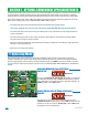
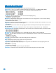
7.1 Operating Mode
The system will automatically open the gate approximately 3 seconds after
loss of AC power. Automatic mode is always used for for gates in general
access applications such as gated communities, apartment complexes, etc.
DO NOT set Switch 1 in the OFF position.
Once AC power is restored, the system’s control board can be set to
“automatically re-key” the gate operator (switch 3 ON) to establish normal
operation, or can be set to require a “manual input” (switch 3 OFF) before
the operator resumes normal operation.
DIP-Switches
2340
Automatic Mode after loss of AC Power,
Switch 1 ON
Restart Options after AC Power is Restored,
Switch 3
1
ON
2 3 4 5 6 7 8
2
5
6
7
8
DIP-Switches
1
ON
2 3 4 5 6 7 8
2
5
6
7
8