
Manual


6500-065-V-12-12
27
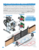
Important: Controls must be installed a minimum
of 10-feet from the gate or installed in such a way
that the person using the control cannot come in
contact with the gate or gate operator.
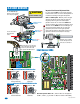
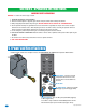
Gate Tracker - DoorKing Access Control System (Model 1833, 1835, 1837 or 1838)
tracker system can be connected. This system can keep track of gate operator cycle
count, shorted inputs, loop detector problems, any forced entry attempts, if the gate
has struck anything during the open or close cycle, power interruptions, etc. For more
detailed information refer to the Tracker Installation and Wiring Manual, DoorKing P/N
2351-010.
Terminal #2 (Full open) required only if the tracker board will activate the gate
operator. Refer to the manual 2351-065 for detailed information.
SW 1, switch 5:
After photo sensor
beam gets obstructed:
OFF- Reverses gate.
See page 24 for more
information.
SW 1
1
ON
2 3 4 5 6 7 8
#5 - Access Control
Devices
20
19
18
17
16
15
14
13
12
11
10
9
8
7
6
5
4
3
2
1
NC NO
1
2
3
4
5
6
7
8
9
13
12
11
10
14
15
16
17
18
19
20
4
1
2
3
Com
Com
Com
4405-010
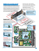
5.2 Control Wiring
Power is
limited to
250 mamps.
SW 1, switch 3 Must be ON.
#4 Com
White
24 Volt
1 amp max.
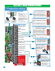
Stand-Alone
Key Switch
#4 - Safety
Opening
Device
Stand-Alone
Keypad
Stand-Alone
Card Reader
Telephone
Entry
“REVERSE” Closing-Direction Photo Sensors
4-Pin Non-Removable Terminal
20-Pin Main
Terminal
Note: All stand-alone
and telephone entry devices must
use a separate power source.
Note: When
using 3-button
control station
AND interlock
switch together,
#3 terminal
(N.C.) must be
wired in series.
Remote Alarm Reset Station
(DKS P/N 1404-080) MUST be mounted
in the line-of-sight of the gate operator.
3-Button Control Station
Use a standard 4-wire 3-button
control station. DoorKing’s
3-wire 3-button control station
CANNOT be used.
Normally Closed Interlock Switch
Radio
Open
#3 Stop N.C.
#2 Close N.O.
#1 Open N.O.
3-Wire
Radio
Receiver
To #4 Com
To #3 Stop N.C.
N.O.
N.C.
Com
Operator Cycling
Lock Engaged
N.O.
N.C.
Com
Operator Stopped
Lock Disengaged
Red
Blue
Alarm
Alarm
Reset
OPEN
STOP
CLOSE
SW 1
1
ON
2 3 4 5 6 7 8
Place jumper
on bottom
2 pins when
using 4-pin
terminal.
3-Pin With
Jumper
Magnetic Lock
#4 Normally Open
#6 Normally Open
#5 Normally Open
#9 Normally Close
Quad Box
Shown
Access
Device
Open
Safety
Open
Power (24-Volt DC) and logic
output. Power is shut off .5 sec.
prior to gate starting and
remains off while gate is
opening and in the
open position.
SW 2, switch 2 ON.
SW 2
1
ON
2 3 4
PUSH
T
O OPERATE
t
ec
hnic
i
an us
e onl
y
(3) Three 115 VAC
Convenience Outlets
Com
24 Volt
Relay
3-Pin
Remote
Terminal
123