Installation/Owner’s Manual Series 6500 Vehicular Swing Gate Operator Use this manual for circuit board 4405-010 Revision E or higher. 6500-065-V-12-12 Date Installed: Installer/Company Name: Circuit Board Serial Number and Revision Letter: Phone Number: Leave Manual with Owner Copyright 2012 DoorKing, Inc. All rights reserved. TM UL 325 Compliant Copyright 2009 DoorKing, Inc. All rights reserved.
SPECIFICATIONS Use this manual for the Model 6500 operators with circuit board 4405-010 Rev E or higher ONLY.
TABLE OF CONTENTS SPECIFICATIONS ASTM F2200 Standard for Gate Construction 4 Important Safety Instructions 4 Instructions regarding intended installation: 4 Important Notices 5 UL 325 Entrapment Protection 6 Glossary 7 Swing Gate Requirements 8 Swing Gate Protection 9 SECTION 1 - INSTALLATION 10 1.1 Underground Conduit Requirements 10 1.2 Concrete Pad 10 1.3 Type of Installations 11-12 1.4 Securing Operator to Pad 13 1.5 Attach Gate Bracket 13 1.6 Determining Arm Lengths 14 1.
TABLE OF CONTENTS SECTION 4 - ENTRAPMENT AND SAFETY PROTECTION 23 4.1 UL 325 Terminal Description 23 4.2 Entrapment and Safety Protection Device Locations 24 4.3 Loop Detector Wiring 25 SECTION 5 - MAIN TERMINAL WIRING 26 5.1 Terminal Descriptions 26 5.2 Control Wiring 27 SECTION 6 - OPERATING INSTRUCTIONS 6.1 Power and Reset Switches 6.2 Shutdown Conditions 28 28 29-30 Soft Shutdown Hard Shutdown 6.
ASTM F2200 Standard for Gate Construction Vehicular gates should be constructed and installed in accordance with ASTM F2200; Standard Specification for Automated Vehicular Gate Construction. For a copy of this standard, contact ASTM directly at 610-832-9585; service@astm.org; or www.astm.org. Important Safety Instructions WARNING - To reduce the risk of injury or death: 1. READ AND FOLLOW ALL INSTRUCTIONS. 2. Never let children operate or play with gate controls. Keep the remote control away from children.
• For gate operators utilizing contact sensors: 1. One or more contact sensors shall be located where the risk of entrapment or obstruction exist, such as at the leading edge, trailing edge, and post mounted both inside and outside of a vehicular horizontal slide gate. 2. One or more contact sensors shall be located at the bottom edge of a vehicular vertical lift gate. 3. One or more contact sensors shall be located at the pinch point of a vehicular vertical pivot gate. 4.
UL 325 Entrapment Protection Class I Class II A vehicular gate operator (or system) intended for use in a home of one-to four single family dwelling, or a garage or parking area associated therewith. A vehicular gate operator (or system) intended for use in a commercial location or building such as a multi-family housing unit (five or more single family units) hotel, garages, retail store or other building servicing the general public.
Glossary GATE - A moving barrier such as a swinging, sliding, raising, lowering, or the like, barrier, that is a stand-alone passage barrier or is that portion of a wall or fence system that controls entrance and/or egress by persons or vehicles and completes the perimeter of a defined area. RESIDENTIAL VEHICULAR GATE OPERATOR – CLASS I - A vehicular gate operator (or system) intended for use in a home of one-to four single family dwelling, or garage or parking area associated therewith.
Swing Gate Requirements The operator is intended for installation only on gates used for vehicles. Pedestrians must be supplied with a separate access opening. The pedestrian access opening shall be designed to promote pedestrian usage. Locate the gate such that persons will not come in contact with the vehicular gate during the entire path of travel of the vehicular gate. (ref. UL 325 56.8.4.
Swing Gate Protection C Non-contact Sensor Minimizes the potential of the gate closing on vehicular or other traffic that loops cannot sense. See pages 23-24 for typical layout locations. Reverse Loop Minimizes the potential of the gate closing when a vehicle is present. Number and placement of loops is dependent on the application. D C D Shadow Loop Provides a hold open command to the operator(s) only if the gate(s) are at the full open position.
SECTION 1 - INSTALLATION Prior to beginning the installation of the swing gate operator, we suggest that you become familiar with the instructions, illustrations, and wiring guide-lines in this manual. This will help insure that your installation is performed in an efficient and professional manner compliant with UL 325 safety and ASTM F2200 construction standards. The proper installation of the vehicular swing gate operator is an extremely important and integral part of the overall access control system.
1.3 Type of Installations 1 Standard Installation Recommended for all gate lengths opening 90°. 46” 90° 14” 23” 38.5” 35” 3” 29.5” 28” 22” Gate opens in approximately 15 seconds. Concrete Pad 46” Operator Installation Concrete Pad Location 2 Alternate Installation Recommended for gates up to 14 feet opening 90°. 42” 90° 13” 23” 32.5” 35” 2” 31.25” 28” 22” Concrete Pad Gate opens in approximately 12 seconds.
3 Compact Installation Recommended for gates NO LARGER THAN 10 FEET opening 90°. 34” 90° 13” 16.5” 26.5” 29.5” 2” 26.5” 28” 22” Concrete Pad 23” Concrete Pad Location Operator Installation 4 Gates Opening Wider than 90° Installation 90° Plus Installation requires the Standard Compact Installation’s concrete pad to be moved 2” away from the gate’s open position. This distance of the gate’s arm will vary depending on how far the gate will open. 42” Varies 23” 35” Gate in desired open position.
1.4 Securing Operator to Pad Permanently attach the operator to the concrete pad using four (4) 3/8” x 3” sleeve anchors (not supplied). 3/8 Sleeve Anchor (Not supplied) 1.5 Attach Gate Bracket A Release hub with release tool. DO NOT REMOVE HUB! B Bolt crank arm to operator. C Slide elbow assembly on crank arm. D Bolt control arm to gate bracket. E Slide control arm into elbow assembly. KEEP ARM ASSEMBLY LEVEL. F Bolt gate bracket to gate.
1.6 Determining Arm Lengths Slide elbow assembly back and fourth, manually opening and closing gate until satisfied with the gate’s 90° open and fully closed positions. Mark and cut off excess arms. Secure arms to elbow assembly with 6 allen screws. Tighten hub and replace release tool. Install safety covers. excess excess 1.7 Installation of Warning Signs This DoorKing Swing Gate Operator is shipped with two warning signs.
2.1 High Voltage Wire Run The distance shown in the chart is measured in Feet from the operator to the power source. If power wiring is greater than the maximum distance shown, it is recommended that a service feeder be installed. When large gauge wire is used, a separate junction box must be installed for the operator connection. The wire table is based on stranded copper wire.
2.3 Bi-Parting Gates Wiring - Dual Gate Operators Connect the Primary/Secondary operators together with DoorKing’s interconnection cable as shown (Different lengths sold separately P/N 2600-75x). High voltage power and low voltage communications are supplied to the secondary operator by DoorKing’s UL approved cable that is run in a single conduit.
SECTION 3 - ADJUSTMENTS The switch settings and adjustments in this chapter should be made after your installation and wiring to the operator(s) is complete. Whenever any of the programming switches on the circuit board are changed, power must be shut-off, and then turned back on for the new setting to take effect. 3.1 4405 Circuit Board Descriptions and Adjustments Auto-Close Timer ON Auto-close timer (when turned on) SW 1, switch 4. SW 1 ON See pages 26 and 27.
3.2 DIP-Switch Settings for 4405 Circuit Board The two DIP-switches located on the circuit board are used to program the operator to operate in various modes and to turn on or off various operating features. Whenever a switch setting is changed, power to the operator must be turned OFF and then turned back on for the new setting to take affect. Check and review ALL switch settings prior to applying power to the operator.
3.2 Continued Switch Definitions ON 1 2 3 4 5 6 7 8 SW 1 (Top 8 Switches) Typical Settings Switch 1 Must OPEN the primary operator’s gate upon initial AC power up and open command. If the FIRST open command begins to close the gate, turn AC power off and reverse this switch. Switch 2 Must OPEN the secondary operator’s gate upon initial AC power up and open command. If the FIRST open command begins to close the gate, turn AC power off and reverse this switch.
3.3 Limit Sensors Important Limit Sensor Adjustment Note: The hub must not slip during operation. Tighten nut to stop any slipping. CAUTION It is very important NOT to cycle the gate operator before the limit sensors are in the correct position or it could cause damage to the gate and operator. DO NOT REMOVE HUB! HUB Loosen set screw to adjust the limit sensor. Release Tool E OS CL Magnetic Sensor Activator Magnetic Close Limit Sensor ONLY turn ON AC power.
3.4 Inherent Reverse Sensors Adjustment This vehicular gate operator is equipped with an inherent adjustable reversing sensor (Type A) used as the primary entrapment protection system according to UL 325 standards. The gate will reverse direction after “physically” encountering an obstruction in either the opening or closing gate cycle.
3.5 Secondary Current Sensor Adjustment (Dual Gates ONLY) The PRIMARY gate operator’s “secondary reversing sensor” uses a secondary current sensing device (Located only in the primary operator) to detect any obstructions “physically” encountered in the SECONDARY gate path when using dual gates. The secondary current sensor uses a sensing coil with a given number of turns through it to monitor the current flow into the secondary operator. Each time the wire passes through the coil, it is considered a turn.
SECTION 4 - ENTRAPMENT AND SAFETY PROTECTION Secondary Entrapment Protection Device: In addition to the inherent reversing sensor system, the Model 6500 has a 6-pin UL 325 terminal for the connection of photo sensors-Type B1 secondary entrapment protection device required by UL 325 standards. Entrapment protection devices must be installed to reduce the risk of injury. Install these devices where the risk of entrapment or a hazard exists while the gate is moving. Specific installations will vary. 4.
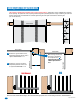
4.2 Entrapment and Safety Protection Device Locations Typical UL Photo Sensor mounting height and distance away from gate. Opening-Direction Photo Sensors Closing-Direction Photo Sensors Gate Frame (Closed) 5” or less Gate Frame (Closed) UL sensor mounted just above top of operator Wall 21” Typical If this space is less than 16 inches, secondary entrapment protection is required in this area.
• Loop detector wiring is shown for DoorKing plug-in loop detectors. If other loop detectors are used, refer to the installation instructions supplied with those detectors for wiring instructions. • If other detectors are used, use a separate power supply to power these detectors. • Loop layout shown is for a typical swing gate application with two-way traffic, or one-way exit only traffic.
SECTION 5 - MAIN TERMINAL WIRING 5.1 Terminal Descriptions Open N.O. Close N.O. Stop N.C. Common 3-Pin with Jumper 4 • Use a standard 4-wire 3-button control station. DoorKing’s 3-wire 3-button control station cannot be used. • When using a 3-button control station AND a interlock device together, #3 terminal (N.C.) must be wired in series. • When gate is closed, input will open gate. • When gate is open and auto close timer SW 1, switch 4 is turned ON, input will re-set and hold timer.
5.2 Control Wiring 4-Pin Non-Removable Terminal N.C. Com N.O. Lock Engaged N.O. Lock Disengaged 5 Power is limited to 250 mamps. 6 7 9 #6 Normally Open “REVERSE” Closing-Direction Photo Sensors #9 Normally Close 10 NO 11 11 12 Com 12 13 14 18 19 20 20 20-Pin Main Terminal 6500-065-V-12-12 See page 24 for more information. Stand-Alone Key Switch 24 Volt 1 amp max. Alarm Alarm Reset Magnetic Lock Power (24-Volt DC) and logic output. Power is shut off .5 sec.
SECTION 6 - OPERATING INSTRUCTIONS IMPORTANT SAFETY INSTRUCTIONS WARNING - To reduce the risk of injury or death: 1. READ AND FOLLOW ALL INSTRUCTIONS. 2. Never let children operate or play with gate controls. Keep the remote control away from children. 3. Always keep people and objects away from gate. NO ONE SHOULD CROSS THE PATH OF THE MOVING GATE. 4. Test the operator monthly. The gate MUST reverse on contact with a rigid object or stop or reverse when an object activates the non-contact sensors.
6.2 Shutdown Conditions Under various entrapment conditions the operator will assume either a soft or hard (alarm) shutdown. To determine what type of reset action is required, you will need to understand how the different entrapment conditions affect the gate operator. Soft Shutdown This occurs in various situations where the inherent or secondary entrapment protection devices have been activated.
Resetting a Hard Shutdown When the operator is in a hard shutdown condition (audio alarm activated or audio alarm “chirps” every 5 seconds), the only way to reset the gate operator and return it to normal operation is to activate the alarm reset input (auxiliary terminals 2 and 3). An alarm-reset switch can be mounted external of the gate operator provided that it is installed in the line of sight of the gate and gate operator. • Before resetting a hard shutdown, determine why the shutdown occurred.
Manual Release A Unlock the cover and rotate sliding door. Never attempt to manually push open any gate with an operator attached to it until you have verified that power to the operator has been shut-off. B Remove release tool and place where shown. C Release hub. Gate can now be manually operated.
SECTION 7 - OPTIONAL CONVENIENCE OPEN ADJUSTMENTS The optional convenience open system installed in your vehicular gate operator is designed as a convenience enhancement only. It is not designed or intended to provide continuous gate operation during a power outage. Its sole purpose is to provide a method to open the vehicular gate to allow unimpeded traffic flow when the gate and access control system is without power.
7.2 DC System Description Do Not Adjust Timer Not Used Do Not Adjust Charging LED Gate will automatically OPEN and stay open during an AC power failure. DIP-Switch 3 setting will determine how operator will return to normal operation AFTER AC power has been restored.
SECTION 8 - MAINTENANCE AND TROUBLESHOOTING Inspection and service of this gate operator by a qualified technician should be performed anytime a malfunction is observed or suspected. High cycle usage may require more frequent service checks. 8.1 Maintenance When servicing the gate operator, always check any secondary (external) reversing devices (loops, photo eyes, etc.) for proper operation.
8.2 Troubleshooting Have a good VOM meter to check voltages and continuity. A Meg-Ohm meter capable of checking up to 500 meg-ohms of resistance is necessary to properly check the integrity of the ground loops. When a malfunction occurs, isolate the problem to one of three areas: 1) the operator, 2) the loop system, 3) the keying devices. Use caution when checking high voltage areas: terminals 17 through 20, the motor capacitor and the motor. 1. Check the input indicator LEDs.
Symptom Possible Solution(s) Gate will not reverse • Check ERD setting. when an obstruction • Make sure operator hub does not slip when gate encounters an obstruction. is encountered. Gate opens a short distance, then stops and reverses. • Check the reversing sensitivity. • Disconnect gate from the gate operator and check that the gate swings freely without any binding. • Continue troubleshooting or replace the circuit board. Gate opens but will not close. • Check the input LEDs.
8.3 Built-in Diagnostics This gate operator is designed with built-in diagnostics that will alert you to potential or existing problems that the microprocessor has detected. Specific fault conditions are checked and the operator will signal that a fault exist through the built-in alarm. Constant tone is heard when power is applied: This indicates that the limit switch wire harness is not connected to the circuit board.
8.4 Accessory Items The following accessory items are available for the model 6500 swing gate operator. Contact Sensors - For use as a secondary entrapment protection device. Miller Edge, Inc., MGO20, MGR20, MGS20 Photo Cell - Non-contact (photo-cells) sensors for use as a secondary entrapment protection device. MMTC, Inc. Model IR55 P/N 8080-010 MMTC, Inc.
8.5 Gearbox Shaft Extension Replacement Crank Arm Only P/N 6500-255 Control Arm Only P/N 2600-714 Complete Arm Kit P/N 6500-430 2 Crank Arm Hub Assembly Remove the TWO allen screws on bottom of hub to remove the complete hub assembly.
Model 6500 1/2 HP 115 VAC Magnetic Close Sensor Magnetic Open Sensor Remote Terminal White Gray Yellow Gray 1/2 HP Red Brown 50uf Capacitor Orange Orange Blue Gray Orange Yellow Red Blue 1 2 3 4 ON SW 2 2 3 4 5 2 3 4 SELF TEST 5 6 7 8 9 6 7 TIME DELAY 8 9 REV SENSE SECONDARY Ground White 1 1 SW 1 EXIT LOOP 1 2 3 4 5 6 7 8 P8 ON P2 10 REV SENSE PRIMARY NC NO 11 12 REVERSE LOOP 13 Current Sensor 14 2 Loops 15 16 17 18 19 20 4405-010 10 11 12 13 14 15 16 17 18 19 20
Model 6500 1/2 HP 115 VAC / Convenience Open Magnetic Close Sensor Magnetic Open Sensor Remote Terminal White Gray Yellow Gray 1/2 HP Red Brown 50uf Capacitor Orange Orange Blue Gray Orange Yellow Diode 2 3 4 5 2 3 7 TIME DELAY 8 9 10 REV SENSE PRIMARY NC NO 11 12 REVERSE LOOP 13 Current Sensor 14 2 Loops 15 16 17 18 19 20 4405-010 Green 6 7 8 9 6 REV SENSE SECONDARY Orange 5 Red 1 2 3 4 ON SW 2 4 SELF TEST Purple 10 11 12 2340 13 14 15 DC Motor Black 16 17 18 19
Model 6500 1 HP 115 VAC Magnetic Close Sensor Magnetic Open Sensor White Brown Gray Yellow Gray 1 HP Remote Terminal Orange Red Orange Blue White Gray Orange Yellow Ground 1 2 3 4 ON SW 2 1 1 SW 1 EXIT LOOP 1 2 3 4 5 6 7 8 P8 ON P2 2 3 4 5 2 3 4 SELF TEST 5 6 7 8 9 6 7 TIME DELAY 8 9 REV SENSE SECONDARY 10 REV SENSE PRIMARY NC NO 11 12 REVERSE LOOP 13 Current Sensor 14 1 Loop 15 16 17 18 19 20 4405-010 10 11 12 13 14 15 16 17 18 19 20 Push to Operate Black Red Po
Model 6500 1 HP 115 VAC / Convenience Open Magnetic Close Sensor Magnetic Open Sensor White Brown Gray Yellow Gray 1 HP Remote Terminal Orange Red Orange Blue White Gray Orange Yellow Diode Ground 1 2 3 4 5 2 3 7 TIME DELAY 8 9 10 REV SENSE PRIMARY NC NO 11 12 REVERSE LOOP 13 Current Sensor 14 1 Loop 15 16 17 18 19 20 4405-010 Green 6 7 8 9 6 REV SENSE SECONDARY Orange 5 Red 1 2 3 4 ON SW 2 4 SELF TEST Purple 10 11 12 2340 13 14 15 DC Motor Black 16 17 18 19 Blac
Model 6500 1/2 HP Secondary Operator 1/2 HP Magnetic Close Sensor Red 50uf Capacitor Magnetic Open Sensor Yellow Orange Blue Red Blue Gray White Blue White Red Ground Model 6500 1/2 HP Secondary Operator/Convenience Open Magnetic Close 50uf Capacitor Sensor 1/2 HP Magnetic Open Sensor Red Yellow Orange Blue Red Orange Purple Blue White Red Ground Diode Gray White White Blue Red 2340 DC Motor Black Red/White Black/White 12 V 3 Amp/Hr – + Batteries DC Power 44 Red/White
Model 6500 1 HP Secondary Operator 1 HP Magnetic Open Sensor Yellow Orange Magnetic Close Sensor Red Blue White Gray Red Blue White Ground Model 6500 1 HP Secondary Operator/Convenience Open 1 HP Magnetic Open Sensor Yellow Orange Magnetic Close Sensor Red Diode Orange Blue Purple White Red Red/White White Gray White Blue Red Ground 2340 DC Motor Black Black/White 12 V 3 Amp/Hr – + Batteries DC Power 6500-065-V-12-12 Red/White 12 V 3 Amp/Hr – + 45
Installation/Owner’s Manual Series 6500 Vehicular Swing Gate Operator Use this manual for circuit board 4405-010 Revision E or higher. 6500-065-V-12-12 www.doorking.com DoorKing, Inc. 120 Glasgow Avenue Inglewood, California 90301 U.S.A. 46 Phone: 310-645-0023 6500-065-V-12-12 Fax: 310-641-1586 Copyright 2009 DoorKing, Inc. All rights reserved.