Owner’s Manual Series 6300 Vehicular Swing Gate Operators DoorKing, Inc. 120 Glasgow Avenue Inglewood, California 90301 U.S.A. Phone: 310-645-0023 Fax: 310-641-1586 www.doorking.com P/N 6300-065 REV E, 4/08 Copyright 2000 DoorKing, Inc. All rights reserved.
Page 2 6300-065-E-4-08
Use this manual with the following models only. Models 6300-080, 6300-081, 6300-082, 6300-083, 6300-084, 6300-085, 6300-086, 6300-087, 6300-088, 6300-089, 6300-090, 6300-091, 6300-092, 6300-093, 6300-094, 6300-095 with 4502010 circuit board.
Glossary GATE: A moving barrier such as a swinging, sliding, raising, lowering, or the like, barrier, that is a stand-alone passage barrier or is that portion of a wall or fence system that controls entrance and/or egress by persons or vehicles and completes the perimeter of a defined area. RESIDENTIAL VEHICULAR GATE OPERATOR – CLASS I: A vehicular gate operator (or system) intended for use in a home of one-to four single family dwelling, or garage or parking area associated therewith.
Entrapment Protection Protection Against Entrapment Gate Operator Category Horizontal Slide, Vertical Lift, Vertical Pivot Swing and Vertical Barrier (arm) Usage Class Primary Secondary Primary Secondary Vehicular I and II A B1, B2 or D A or C A, B1, B2, C or D Vehicular III A, B1 or B2 A, B1, B2, D or E A, B1, B2 or C A, B1, B2, C, D or E Vehicular IV A, B1, B2 or D A, B1, B2, D or E A, B1, B2, C or D A, B1, B2, C, D or E TYPE A: TYPE B1: TYPE B2: TYPE C: TYPE D: TYPE E: 6300-065
Important Notices Vehicular gate operator products provide convenience and security. However, gate operators must use high levels of force to move gates and most people underestimate the power of these systems and do not realize the potential hazards associated with an incorrectly designed or installed system.
Important Safety Instructions WARNING - To reduce the risk of injury or death: 1. 2. 3. 4. 5. 6. 7. 8. READ AND FOLLOW ALL INSTRUCTIONS. Never let children operate or play with gate controls. Keep the remote control away from children. Always keep people and objects away from gate. NO ONE SHOULD CROSS THE PATH OF THE MOVING GATE. Test the operator monthly.
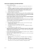
Instructions regarding intended installation: • 1. 2. 3. 4. Install the gate operator only if: The operator is appropriate for the construction of the gate and the usage class of the gate. All openings of a horizontal slide gate are guarded or screened from the bottom of the gate to a minimum of 4 feet (1.22 m) above the ground to prevent a 2 ¼ inch (57.
• 1. 2. 3. 4. 5. 7. For gate operators utilizing contact sensors: One or more contact sensors shall be located where the risk of entrapment or obstruction exist, such as at the leading edge, trailing edge, and post mounted both inside and outside of a vehicular horizontal slide gate. One or more contact sensors shall be located at the bottom edge of a vehicular vertical lift gate. One or more contact sensors shall be located at the pinch point of a vehicular vertical pivot gate.
Swing Gate Requirements The operator is intended for installation only on gates used for vehicles. Pedestrians must be supplied with a seperate access opening. The pedestrian access opening shall be designed to promote pedestrian usage. Locate the gate such that persons will not come in contact with the vehicular gate during the entire path of travel of the vehicular gate. (ref. UL325 56.8.4.
Swing Gate Protection Reverse 1 6 5 Pedestrian Access 4 5 Shadow 2 Sidewalk Reverse 1 6 Automatic Exit 3 1 Reverse loops minimize the potential of the gate closing when a vehicle is present . Number and placement of loops is dependent on the application. 2 Shadow loop provides a hold open command to the operator (s) only if the gate(s) are in the full open position. 3 Automatic exit loop (optional) will provide an open command to the gate operator(s) when a vehicle is exiting the property.
Table of Contents Section 1 – Installation 1.1 Specifications ...........................................................................................................................................15 1.2 Mounting Post / Base Plate Installation 1.3 1.4 1.2.1 Post Mount Operator ................................................................................................................16 1.2.2 Pad Mount Operator..................................................................................
Section 4 – Operating Instructions 4.1 4.2 Power and Reset Switches ......................................................................................................................41 Shutdown Conditions 4.2.1 4.3 Soft Shutdown ..........................................................................................................................42 4.2.2 Resetting a Soft Shutdown.......................................................................................................42 4.2.
Page 14 6300-065-E-4-08
SECTION 1 - INSTALLATION Prior to beginning the installation of the swing gate operator, we suggest that you become familiar with the instructions, illustrations, and wiring guide-lines in this manual. This will help insure that your installation is performed in an efficient and professional manner. The proper installation of the vehicular swing gate operator is an extremely important and integral part of the overall access control system.
1.2 Mounting Post/Base Plate Installation 1.2.1 Post Mount 1. 2. Screw the two mounting posts supplied into the operator mounting plate. Using the dimensions shown below, locate the mounting plate/post assembly as shown. Note that when the mounting plate/post assembly is properly located, the operator output shaft (Point C) will intersect an imaginary line drawn from the gate mounting bracket in the closed position (A1) to the gate mounting bracket in the open position (A2).
• • • The height requirement is determined by adjusting the mounting plate/post assembly so that the top of the mounting plate is 5 inches above the top of the gate rail (Figure 4). This will allow you to mount the gate bracket onto the bottom rail of the gate and will keep the crank and connecting arms level (see page 22, Figure 10).
1.2.2 Pad Mount 1. Using the dimensions shown below, locate the operator pad mount assembly as shown. Note that when the operator pad mount assembly is properly located, the operator output shaft (Point C) will intersect an imaginary line drawn from the gate mounting bracket in the closed position (A1) to the gate mounting bracket in the open position (A2). Once the location of the operator pad mount assembly has been determined, construct a form for the concrete pad according to Figure 3.
• The concrete pad is sized so that there is a minimum of three (3) inches of concrete around the perimeter of the pad. • Attach the gate bracket to the gate so that the top of the mounting plate is 5 inches above the top of the gate bracket as shown in Figure 7. This will keep the crank and connecting arms level (see page 22, Figure 10).
1.3 Mounting the Operator 1. 2. 3. Remove the operator from the shipping carton. Remove the cover from the operator. It is advisable to remove the conduit knockouts (as required) prior to mounting the operator onto the operator base plate. 1.3.1 Post Mounted Operators 1. 2. 3. 4. Place the operator on its side and remove 6 bolts and 4 nuts from the bottom frame (Figure 8). Gently place the operator on the mounting post assembly being sure to align all 6 nut plates and the 4 mounting bolts.
1.3.2 Pad Mounted Operators 1. Place the operator on its side and remove 4 bolts and 4 nuts from the bottom frame (Figure 9). 2. Gently place the operator on the pad mounting assembly being sure to align all 4 nut plates and the 4 mounting bolts. 3. Replace the 4 bolts and 4 nuts removed in step 1 to secure the operator to the pad mounting assembly. 4. Route conduits into the operator at this time.
1.4 Arm Assembly and Installation 12 Hinge Pad Mount 24 Post Mount Gate Bracket 37.5 Mounting Pad Figure 10 1.4.1 Crank Arm Assembly 1. Attach the crank arm and crank power arm to the operator output shaft using the supplied hardware (Figure 11). Position the arm so that it is pointing towards the gate. 2. Do not insert the lock pin or lock into the crank arm assembly at this time. It will be installed later. 3.
To Operator To Gate Figure 12 4. Slide the connector assembly (Figure 12) onto the crank arm so that the flange is away from the gate. 5. The connector assembly must be positioned on the crank arm at the correct distance from the operator shaft to allow the gate to open a full 90º (refer to figure 11 on the preceding page). 6. Adjust the connector assembly on the crank arm so that the distance from the center of the operator output shaft to the center of the pivot on the connector assembly is 24 inches.
1.4.3 Test Your Installation Gate Closed When the gate is fully closed, the drive and connecting arms should be in a straight line as shown in Figure 14. • Manually open the gate. The connecting arm should rotate beneath the drive arm and output shaft. When the gate is fully open, the drive arm should be directly over the connecting arm as shown in Figure 15. • If the gate does not open a full 90°, this means that the drive arm is too short. Re-check this measurement and reset the drive arm length.
1.6 Setup for Gates Opening other than 90° 1.6.1 Determine Location of the Operator 24.00 28.00 A1 36.00 13.00 Operator Housing 105.2° 44.5 A1:A2 A2 62.25 A1:C C 22.25 (A1:A2) / 2 = Crank Arm 1. 2. 3. 4. A1 to A2 = 44.5 inches. 44.5 divided by 2 = 22.25 inches (Crank Arm length). A1 to C = 62.25 inches. 62.25 minus 22.25 = 40 inches (Connecting Arm length). 42.00 Minimum side room required for shown mounting position.
1.6.2 Arm Length Calculations After the operator has been installed, use the following steps to determine the correct crank arm and connecting arm lengths for the installation. The measurements are from the pivot point to the pivot point of each arm – they are not the overall length of the arm. 1. 2. Page 26 Measure the distance from point A1 to point A2 (44.5 inches in our example). Divide this measurement by 2 (22.25 inches in our example).
SECTION 2 – WIRING Before attempting to connect any wiring to the operator, be sure that the circuit breaker in the electrical panel is in the OFF position. Permanent wiring must be installed to the operator as required by local electrical codes. It is recommended that a licensed electrical contractor perform this work.
2.1 High Voltage Connections Use Table 1 to determine high voltage wire size requirements. The distance shown in the chart is measured in feet from the operator to the power source. If power wiring is greater than the maximum distance shown, it is recommended that a service feeder be installed. When large gauge wire is used, a separate junction box must be installed for the operator connection. The wire table is based on stranded copper wire.
2.2 Control Wiring B Diagram at right is for illustration purposes. The actual placement of the secondary protection devices is dependent on the specific installation requirements. Secondary entrapment protection devices must be installed with this gate operator. This protection may be provided by non-contact or contact sensors, or a combination of both. A A Secondary device wiring shows inputs to the circuit board only. Photo-cells must be supplied with power.
2.3 Loop Detector Wiring Loops and loop detectors MUST be installed with this gate operator to help prevent the gate from accidentally closing on vehicular traffic. Reverse Loop detector wiring is shown for DoorKing plug-in loop detectors only. If other loop detectors are used, refer to the installation instructions supplied with those detectors for wiring instructions. If other detectors are used, use a separate power supply to power these detectors.
2.4 Auxiliary Device Wiring 1 The auxiliary stop switch will stop a moving gate when activated or will prevent the gate operator from starting when activat ed. Note that this input is normally open and that a switch closure is required to activate the stop function . Because of this, the auxiliary stop shown must NEVER be used as a safety interlock device. 2 Jumper is placed across terminals 13 and 14 ONLY WHEN THE AUXILIARY STOP INPUT IS USED.
2.5 Primary / Secondary (Dual) Gate Wiring 1 Connect the Primary / Secondary interconnection wiring as shown. Wire colors are based on DoorKing interconnection cable (P/N 2600-75x). 2 Place a jumper from terminal 15 to terminal 16 in the PRIMARY operator. 3 Place a jumper from terminal 19 to terminal 20 in the SECONDARY operator. 4 Plug a two-channel (P/N 9409-010) loop detector into the REVERSE loop port in the PRIMARY operator. Connect loops and loop detector as shown.
2.6 1. 2. 3. 4. 5. 6. 7. 8. 9. 10. 11. 12. 13. 14. 15. 16. 17. 18. 19. 20. Main Terminal Description 115 VAC Neutral 115 VAC Neutral Output To Slave Operator 115 VAC Power Input 115 VAC Motor Power (Open) 115 VAC Motor Power (Close) Not used 24 VAC Radio Receiver Power Only (250 ma. maximum) 12 VAC Magnetic Counter Power Only (150 ma. maximum) PULSE 1 Input From Master Operator PULSE 2 Input From Slave Operator SINGLE BUTTTON ACTIVATION INPUT 1 When gate is closed, input will open gate.
2.7 Auxiliary Terminal Description The auxiliary terminal is located on the 4502 circuit board just to the right of main terminals 18 and 19. Auxiliary terminals are numbered 1 through 8. 1. 2. 3. 4. 5. 6. 7. 8. Page 34 ALARM OUTPUT Provides power to activate the entrapment alarm. ALARM RESET INPUT Input to reset the operator after an entrapment alarm. COMMON Common for alarm output and alarm reset input. TRACKER DATA Supplies gate operator data to Tracker expansion board (P/N 2351-010).
SECTION 3 – ADJUSTMENTS The switch settings and adjustments in this chapter should be made after your installation and wiring to the operator(s) is complete. Whenever any of the programming switches on the circuit board are changed, power must be shut-off, and then turned back on for the new setting to take effect. 3.1 Circuit Board Adjustments • Set the DIP-switches on the circuit board to the desired setting. See switch-setting charts in section 3.2.
3.2 Switch Settings The two DIP-switches located on the circuit board are used to program the operator to operate in various modes and to turn on or off various operating features. Whenever a switch setting is changed, power to the operator must be turned OFF and then turned back on for the new setting to take affect. Check and review ALL switch settings prior to applying power to the operator.
3.2.1 SW 1 (Top Switch) Description and Function Switches 1-2: These work in conjunction with each other and determine when the relay on the board will be activated. This relay can be used as a switch for various functions such as illuminating a warning light when the gate is moving, or turning on a green light when the gate is full open. This relay is not available for these uses if it is being used for the shadow loop function.
3.3 Automatic Limit Adjustment This gate operator does not use any limit switches or run timers to adjust the gate open and close positions. The gate open and close positions are determined by the physical stops on the crank arm. The gate operator will automatically measure the travel distance required and set its "limits" from this measurement during this initial automatic sequence.
3.4 Entrapment Sensing Adjustment This vehicular gate operator is equipped with an inherent adjustable clutch (Type C) that is used as the primary entrapment sensing system. The clutch will slip upon sensing an obstruction in either the opening or closing gate cycle and will cause the gate operator to reverse direction should an obstruction be encountered. For this system to function correctly, the gate must be properly installed and work freely in both directions.
Page 40 6300-065-E-4-08
SECTION 4 – OPERATING INSTRUCTIONS IMPORTANT SAFETY INSTRUCTIONS WARNING - To reduce the risk of injury or death: 1. 2. 3. 4. 5. 6. 7. 8. 4.1 READ AND FOLLOW ALL INSTRUCTIONS. Never let children operate or play with gate controls. Keep the remote control away from children. Always keep people and objects away from gate. NO ONE SHOULD CROSS THE PATH OF THE MOVING GATE. Test the operator monthly.
4.2 Shutdown Conditions Under various entrapment conditions the operator will assume either a soft or hard shutdown (alarm) condition. To determine what type of reset action is required, you will need to understand how the different entrapment conditions affect the gate operator. 4.2.1 Soft Shutdown This occurs in various situations where the inherent or secondary entrapment protection devices have been activated.
4.2.3 Hard Shutdown A hard shutdown condition occurs when the inherent entrapment protection system has sensed two consecutive obstructions before the gate reaches the full open or closed position. • Example: The gate is closing and the inherent entrapment protection system senses an obstruction and causes the gate to reverse direction. As the gate begins to run in the open direction, a second obstruction is sensed prior to the gate reaching the full open position.
4.3 Manual Gate Operation This operator is equipped with a manual release system that will allow the gate to be pushed open in the event of a power outage or equipment failure. NOTE: Never attempt to manually push open any gate with an operator attached to it until you have verified that power to the operator has been shut-off. 4.3.1 Emergency Vehicle Access Conditions The automatic vehicular gate system must be designed to allow access to emergency vehicles under different operating conditions. 1.
To G at e on ne ct or Ar m bl y on ne ct or As se m C m Ar ra nk O pe ra to r C ! LL PU ele R e as If an attempt is made to force the gate open under normal operating conditions (AC power present), a tamper protect circuit will detect the forced entry and will start the motor to return the gate to the closed position. If Gate Tracker reporting is in use, a forced entry attempt transaction will be sent to the DoorKing access control system at this time. To • C 1.
Page 46 6300-065-E-4-08
SECTION 5 – MAINTENANCE AND TROUBLESHOOTING Inspection and service of this gate operator by a qualified technician should be performed anytime a malfunction is observed or suspected. High cycle usage may require more frequent service checks. 5.1 Maintenance When servicing the gate operator, always check any secondary (external) reversing devices (loops, photo eyes, etc.) for proper operation.
5.2 Troubleshooting Have a good VOM meter to check voltages and continuity. A Meg-Ohm meter capable of checking up to 500 meg-ohms of resistance is necessary to properly check the integrity of the ground loops. When a malfunction occurs, isolate the problem to one of three areas: 1) the operator, 2) the loop system, 3) the keying devices. Use caution when checking high voltage areas: terminals 1 through 6, the motor capacitor and the motor. 1. Check the input indicator LEDs.
Gate opens a short distance, then stops and reverses. Gate opens but will not close. Gate closes but will not open. Gate starts to close, then reverses to open. Gate closes and then re-opens. Alarm sounds for 5 minutes and then beeps once every 5 seconds. Operator will not run. Battery backup system will not open gate upon AC power outage. 6300-065-E-4-08 • Check that the clutch is adjusted properly and is not slipping.
5.3 Accessory Items The following accessory items are available for the model 6300 swing gate operators. Contact Sensors Photo Cell Loop Detector Magnetic Lock Remote Reset Control Station Control Station Interconnect Cable Time Clock Torsion Rods Hinges Surge Devices Moly D Grease Gate Scale Speed Bumps Page 50 Contact sensors for use as a secondary entrapment protection device. Miller Edge, Inc.
1 White 2 3 Blue 4 Red 5 6 7 Yellow 50 uf Cap 8 Brown 9 Magnetic Pickup 10 11 Blue Red 4502-010 Circuit Board 12 13 Motor ½ HP 14 15 16 17 18 White 19 20 White Yellow Red Alarm Reset Alarm 115 VAC Convenience Outlets White White Black Black Black Operator Power Chassis Ground Black White Earth Ground Green 115 VAC Input DOORKING, INC., INGLEWOOD, CA 90301 Title: Date: 6300-065-E-4-08 Model 6300 Wire Diagram ½ HP 115 VAC 10/07 Dwg. No. 4502-05-115-1 Rev.
1 White 2 3 Blue 4 Red 5 6 7 Yellow 50 uf Cap 8 Brown 9 Magnetic Pickup 4502-010 Circuit Board 10 11 Blue 12 Red 13 Motor ½ HP 14 15 16 17 18 White 19 20 Yellow White Red Alarm Reset Alarm Green Red White White DC Power Black 1 2 3 4 5 6 7 8 9 10 2340 Circuit Board Red Black DC Motor 115 VAC Convenience Outlets White White Black Black Black Operator Power Chassis Ground Black White Earth Ground Green 115 VAC Input DOORKING, INC.
1 White 2 3 Blue 4 Red 5 6 7 Yellow 50 uf Cap 8 Brown 9 Magnetic Pickup 10 11 Blue Red 4502-010 Circuit Board 12 13 14 15 16 17 18 White 19 20 White Yellow Red Alarm Reset White Black White Brown Alarm Step-down Transformer White Blue Black Blue Operator Power 115 VAC Convenience Outlets Blue Black Brown White 230V Green White Black Black/White Black Blue Black Black Black Brown 460V 230/460 V Input Green For 3 Phase power input, use 2 power legs and cap the third.
1 White 2 3 Blue 4 Red 5 6 7 Yellow 50 uf Cap 8 Brown 9 Magnetic Pickup 4502-010 Circuit Board 10 11 Blue 12 Red 13 14 15 16 17 18 White 19 20 Yellow White Red Alarm Reset White Black Brown Alarm White Green Red White White Step-down Transformer DC Power White Black Red Blue Blue Black Black 1 2 3 4 5 6 7 8 9 10 2340 Circuit Board DC Motor Operator Power 115 VAC Convenience Outlets Blue Black Brown 230V White White Black Black Green White Black/White Black B
1 White 2 3 Blue 4 Red 5 6 7 Yellow 8 Brown 9 Magnetic Pickup 10 11 Blue Red 4502-010 Circuit Board 12 13 Motor 1 HP 14 15 16 17 18 White 19 20 White Yellow Red Alarm Reset Alarm 115 VAC Convenience Outlets White White Black Black Black Operator Power Chassis Ground Black White Earth Ground Green 115 VAC Input DOORKING, INC., INGLEWOOD, CA 90301 Title: Date: 6300-065-E-4-08 Model 6300 Wire Diagram 1 HP 115 VAC 10/07 Dwg. No. 4502-1-115-1 Rev.
1 White 2 3 Blue 4 Red 5 6 7 Yellow 8 Brown 9 Magnetic Pickup 4502-010 Circuit Board 10 11 Blue 12 Red 13 Motor 1 HP 14 15 16 17 18 White 19 20 Yellow White Red Alarm Reset Alarm Green Red White White DC Power Black 1 2 3 4 5 6 7 8 9 10 2340 Circuit Board Red Black DC Motor 115 VAC Convenience Outlets White White Black Black Black Operator Power Chassis Ground Black White Earth Ground Green 115 VAC Input DOORKING, INC.
1 White 2 3 Blue 4 Red 5 6 7 Yellow 8 Brown 9 Magnetic Pickup 10 11 Blue Red 4502-010 Circuit Board 12 13 Motor 1 HP 14 15 16 17 18 White 19 20 White Yellow Red Alarm Reset White Black White Brown Alarm Step-down Transformer White Blue Black Blue Operator Power 115 VAC Convenience Outlets Blue Black Brown White 230V Green White Black Black/White Black Blue Black Black Black Brown 460V 230/460 V Input Green For 3 Phase power input, use 2 power legs and cap the third.
1 White 2 3 Blue 4 Red 5 6 7 Yellow 8 Brown 9 Magnetic Pickup 4502-010 Circuit Board 10 11 Blue 12 Red 13 Motor 1 HP 14 15 16 17 18 White 19 20 Yellow White Red Alarm Reset White Black Brown Alarm White Green Red White White Step-down Transformer DC Power White Black Red Blue Blue Black Black 1 2 3 4 5 6 7 8 9 10 2340 Circuit Board DC Motor Operator Power 115 VAC Convenience Outlets Blue Black Brown 230V White White Black Black Green White Black/White Black
6300-065-E-4-08 Page 59