
Manual


Page 35
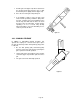
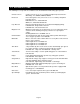
1. Pull the gate arm (figure 38) that is attached to
the operator shaft away from the gate so that
the knuckle joint is slightly "broken" (figure 39).
2. Go to the end of the gate and pull it open.
• If an attempt is made to force the gate open
under normal operating conditions (AC power
present), a tamper protect circuit will detect the
forced entry and will start the motor to return
the gate to the closed position. If Gate Tracker
reporting is in use, a forced entry attempt
transaction will be sent to the DoorKing access
control system at this time.
4.3.3 MANUAL RELEASE
In addition to FAIL-SAFE manual operation, this
operator also employees a locked release pin to place
the gate in manual operation when primary (AC) power
is removed.
• Be sure that primary (AC) and backup (DC)
power is removed or shut-off prior to placing the
gate operator in manual operation.
• Unlock and remove the padlock on the operator
crank arm (figure 38) and then pull the release
pin.
• The gate can now be manually operated.
To Gate
T
o
O
per
ator
C
rank Arm
Connector Arm
Connector Assembly
Figure 39
Figure 38
To
G
a
te
To Op
e
rator
C
r
ank Arm
Connector Arm
C
on
nect
or
Ass
em
bl
y
PUL
L!
Ma
nua
l
P
a
dl
oc
k
R
el
ea
s
e Pin