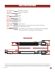
Actuator Arm and Control Box Mounting 6003 Vehicular Swing Gate Operator To wire this operator and complete the installation, refer to a specific control box “Wiring/Owner’s manual”. 6003-065-Q-2-12 CL OS E OP EN Copyright 2012 DoorKing, Inc. All rights reserved. TM UL 325 Compliant Copyright 2009 DoorKing, Inc. All rights reserved.
6003 SPECIFICATIONS Class of Operation Model 6003 - UL 325 Class I Type of Gate Vehicular Swing Gates Only Actuator Arm Voltage 24 VDC Current 3 Amps Motor RPM 1400 Maximum Thrust 300 daN Max Gate Weight 300 Lbs.
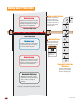
TABLE OF CONTENTS SPECIFICATIONS 6003 Specifications 1 ASTM F2200 Standard for Gate Construction 3 Important Safety Instructions 3 Instructions regarding intended installation: 3 Important Notices 4 UL 325 Entrapment Protection 5 Glossary 6 Swing Gate Requirements 7 Swing Gate Protection 8 INSTALLATION Manual Key Release 9 9 Gate “Opens to the Inside” Installation 10 Gate “Opens to the Outside” Installation 11 Mounting Actuator Arm 12 Mounting Control Box with Conduit 2 1 13-14
ASTM F2200 Standard for Gate Construction Vehicular gates should be constructed and installed in accordance with ASTM F2200; Standard Specification for Automated Vehicular Gate Construction. For a copy of this standard, contact ASTM directly at 610-832-9585; service@astm.org; or www.astm.org. Important Safety Instructions WARNING - To reduce the risk of injury or death: 1. READ AND FOLLOW ALL INSTRUCTIONS. 2. Never let children operate or play with gate controls. Keep the remote control away from children.
• For gate operators utilizing contact sensors: 1. One or more contact sensors shall be located where the risk of entrapment or obstruction exist, such as at the leading edge, trailing edge, and post mounted both inside and outside of a vehicular horizontal slide gate. 2. One or more contact sensors shall be located at the bottom edge of a vehicular vertical lift gate. 3. One or more contact sensors shall be located at the pinch point of a vehicular vertical pivot gate. 4.
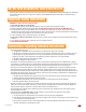
UL 325 Entrapment Protection Class I Class II A vehicular gate operator (or system) intended for use in a home of one-to four single family dwelling, or a garage or parking area associated therewith. A vehicular gate operator (or system) intended for use in a commercial location or building such as a multi-family housing unit (five or more single family units) hotel, garages, retail store or other building servicing the general public.
Glossary GATE - A moving barrier such as a swinging, sliding, raising, lowering, or the like, barrier, that is a stand-alone passage barrier or is that portion of a wall or fence system that controls entrance and/or egress by persons or vehicles and completes the perimeter of a defined area. RESIDENTIAL VEHICULAR GATE OPERATOR – CLASS I - A vehicular gate operator (or system) intended for use in a home of one-to four single family dwelling, or garage or parking area associated therewith.
Swing Gate Requirements The operator is intended for installation only on gates used for vehicles. Pedestrians must be supplied with a separate access opening. The pedestrian access opening shall be designed to promote pedestrian usage. Locate the gate such that persons will not come in contact with the vehicular gate during the entire path of travel of the vehicular gate. (ref. UL325 56.8.4.
Swing Gate Protection C Non-contact Sensor Minimizes the potential of the gate closing on vehicular or other traffic that loops cannot sense. See page 16 for typical layout locations. Reverse Loop Minimizes the potential of the gate closing when a vehicle is present. Number and placement of loops is dependent on the application. D Non-Secure Side of Gate C D Secure Side of Gate Shadow Loop Provides a hold open command to the operator(s) only if the gate(s) are at the full open position.
INSTALLATION Sa Du al mp le I 1 Ga 15 VA te Op C Sta era nd tor ard s “ Co Op nt en rol ing Bo to x the I nst all ati on nsi de ” Prior to beginning the installation of the swing gate operator, we suggest that you become familiar with the instructions and illustrations in this manual. This will help insure that your installation is performed in an efficient and professional manner compliant with UL 325 safety and ASTM F2200 construction standards.
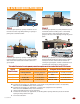
“Opening to the Inside” Installation Front Bracket Pivot Point Rear Bracket Pivot Point 47.5” Closed Position Do not install the actuator in fully extended (Bottomed out) position. This will damage the Cut Off arm. See page 12 to prevent Excess this from happening. Bracket Front Bracket Closed Position 7” Gate Hinge Pivot Point 7” Attaching Brackets to Surfaces Bolt or weld brackets to gate and support post/wall.
“Opening to the Outside” Installation Front Bracket Pivot Point Attaching Brackets to Surfaces Bolt or weld brackets to gate and support post/wall. Reinforcing steel plate for sleeve anchors if desired. (Not Supplied) Front Bracket Bolt or weld to gate. Rear Bracket Bolt rear support bracket to fabricated steel plate with supplied lock nuts. Note: The brackets must be perpendicular (Plumb) to the gate and wall/post and horizontally level. If welding brackets to surfaces, weld completely around brackets.
Mounting Actuator Arm Gate must be in good working condition before the actuator arm can be installed. Determine what direction the actuator arm will open the gate: “Opening to the Outside” or “Opening to the Inside” Installation (See 2 previous pages). Gate Support Bar A support bar that spans the entire length of the gate must be installed to keep the pickets from bending.
Mounting Control Box with Conduit Permanent wiring must be installed to the operator as required by local electrical codes (See the 115 VAC control box Wiring/Owner’s manual or Solar control box Wiring/Owner’s manual to wire operator). It is recommended that a licensed electrical contractor perform this work. Check local building codes prior to installing any permanent wiring to ensure all wiring and connections comply with local electrical code requirements.
Mounting Control Box Continued ONLY Mount One 24 Volt Solar Panel! The 24 volt - 10 watt or 20 watt solar panel must be correctly installed for the system to function correctly. See the solar control box Wiring/Owner’s manual for more information about concerns, considerations and recommendations for proper solar panel positioning and mounting. DO NOT use a 12 volt solar panel. Damage WILL occur!! 24 Volt 10 Watt Solar Panel P/N 2000-077 • One 24 V 10 watt panel required for 18 Amp/Hr batteries.
Install Warning Signs This DoorKing Swing Gate Operator is shipped with two warning signs. The purpose of the warning sign is to alert uninformed persons, and to remind persons familiar with the gate system, that a possible hazard exists so that appropriate action can be taken to avoid the hazard or to reduce exposure to the hazard. See page 8 for suggested mounting positions of signs.
Photo Sensor Positions “Opening to the Inside” Secondary Entrapment Protection Device: In addition to the inherent reversing sensor system, the Model 6003 has a 6-pin UL 325 terminal for the connection of photo sensors-Type B1 secondary entrapment protection device required by UL 325 standards (see 115 VAC or Solar control box wiring manual). Entrapment protection devices must be installed to reduce the risk of injury.
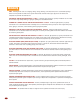
Accessory Items The following accessory items are available for the model 6003 swing gate operator. Control Box Types - Fully controls actuator arm(s) with built-in battery back-up system. P/N 4302-111 - 115 VAC Standard Control Box, 115 VAC 60 Hz Input to box, 24 VDC output to gate operator. P/N 4302-112 - 115 VAC Deluxe Control Box, 115 VAC 60 Hz Input to box, 24 VDC output to gate operator. 3-115 VAC convenience outlets.
6003 Primary/Secondary 4302 Circuit Board Connection A A Blue and Brown Motor Blue and Brown Motor 1 2 3 4 5 6 7 1 2 3 4 5 6 7 Brown 1 Blue 2 Orange 3 Red 4 Yellow 5 Green 6 Green/Yellow 7 1 2 3 4 5 6 7 Secondary Connection ONLY 1 2 3 4 5 6 7 1 2 3 4 5 6 7 Brown 1 Blue 2 Orange 3 Red 4 Yellow 5 Green 6 Green/Yellow 7 1 2 3 4 5 6 7 Gray White Wires White Wires Primary Connection ONLY 1 Gray 2 3 4 5 6 7 8 9 10 11 12 13 14 15 16 17 18 19 20 Limit Assembly Purple Limit Assembly Purp
Actuator Arm and Control Box Mounting 6003 Vehicular Swing Gate Operator To wire this operator and complete the installation, refer to the specific control box “Wiring/Owner’s manual”. 6003-065-Q-2-12 www.doorking.com DoorKing, Inc. 120 Glasgow Avenue Inglewood, California 90301 U.S.A. Phone: 310-645-0023 Fax: 310-641-1586 Copyright 2009 DoorKing, Inc. All rights reserved.