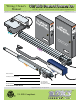
Wiring / Owner’s Manual 115 VAC Control Boxes for 6002, 6003, 6004 and 6400 gate operators Use this manual for circuit board 4302-010 Revision A or higher. O P E R A T O R 53 38 2 S Cotan nt dar ro d lB ox HP U L A R G A T E TO MS 5 7 OR UL-32 TO . 24 NF ED NO CO ANSI/ IFI 2.2 RT CE SA C2 N/C CA S AS L CL DE MO E H IC AS PH E V Hz CA 60 oo d, L gl In , In c.
115 VAC CONTROL BOXES SPECIFICATIONS Class of Operation Type of Gate Voltage / Phase Back-Up Power Circuit Board Model Entrapment Protection Models 6002, 6003, 6004 and 6400 - UL325 Class I Residential Vehicular Automated Gates Only 115 VAC 60 Hz Single Phase Input Power – 24 VDC Output Power to Gate Operators 24 VDC battery power during power outages. 4302-010 revision A or higher.
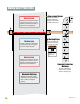
TABLE OF CONTENTS SPECIFICATIONS 115 VAC Control Boxes Specifications ASTM F2200 Standard for Gate Construction Important Safety Instructions Instructions regarding intended installation: Important Notices UL 325 Entrapment Protection Glossary Swing Gate Requirements Swing Gate Protection SECTION 1 - WIRING 1.1 1.1 1.2 1.3 1.4 1.5 1.
ASTM F2200 Standard for Gate Construction Vehicular gates should be constructed and installed in accordance with ASTM F2200; Standard Specification for Automated Vehicular Gate Construction. For a copy of this standard, contact ASTM directly at 610-832-9585; service@astm.org; or www.astm.org. Important Safety Instructions WARNING - To reduce the risk of injury or death: 1. READ AND FOLLOW ALL INSTRUCTIONS. 2. Never let children operate or play with gate controls. Keep the remote control away from children.
• For gate operators utilizing contact sensors: 1. One or more contact sensors shall be located where the risk of entrapment or obstruction exist, such as at the leading edge, trailing edge, and post mounted both inside and outside of a vehicular horizontal slide gate. 2. One or more contact sensors shall be located at the bottom edge of a vehicular vertical lift gate. 3. One or more contact sensors shall be located at the pinch point of a vehicular vertical pivot gate. 4.
UL 325 Entrapment Protection Class I Class II A vehicular gate operator (or system) intended for use in a home of one-to four single family dwelling, or a garage or parking area associated therewith. A vehicular gate operator (or system) intended for use in a commercial location or building such as a multi-family housing unit (five or more single family units) hotel, garages, retail store or other building servicing the general public.
Glossary GATE - A moving barrier such as a swinging, sliding, raising, lowering, or the like, barrier, that is a stand-alone passage barrier or is that portion of a wall or fence system that controls entrance and/or egress by persons or vehicles and completes the perimeter of a defined area. RESIDENTIAL VEHICULAR GATE OPERATOR – CLASS I - A vehicular gate operator (or system) intended for use in a home of one-to four single family dwelling, or garage or parking area associated therewith.
Swing Gate Requirements The operator is intended for installation only on gates used for vehicles. Pedestrians must be supplied with a separate access opening. The pedestrian access opening shall be designed to promote pedestrian usage. Locate the gate such that persons will not come in contact with the vehicular gate during the entire path of travel of the vehicular gate. (ref. UL325 56.8.4.
Swing Gate Protection C Non-contact Sensor Minimizes the potential of the gate closing on vehicular or other traffic that loops cannot sense. Reverse Loop Minimizes the potential of the gate closing when a vehicle is present. Number and placement of loops is dependent on the application. D C D Shadow Loop Provides a hold open command to the operator(s) only if the gate(s) are at the full open position. D Warning Signs Permanently mounted and easily visible from either side of the gate.
SECTION 1 - WIRING Before attempting to connect any wiring to the control box, be sure that the circuit breaker in the electrical panel is in the OFF position. Permanent wiring must be installed to the control box as required by local electrical codes. It is recommended that a licensed electrical contractor perform this work.
1.2 Wiring Operators to 4302 Circuit Board Primary or Secondary Operator Cable Terminal Brown Wire Blue Wire Orange Wire Red Wire Yellow Wire Green Wire Green/Yellow Wire Not Used Operator Terminal Note: The 8-pin terminals can be unplugged from circuit board for easy wire connections.
1.3 Secondary Entrapment Protection Wiring In addition to the inherent entrapment sensing system, this operator has provisions for the connection of a non-contact (type B1) secondary entrapment protection device. This is required by UL 325 standards. Entrapment protection devices are required to reduce the risk of injury. Install sensors where the risk of entrapment or obstruction exists while gate is moving. UL 325 Terminal 1 2 3 4 5 6 PHOTO OPEN (Photo Sensors) Stops gate movement in the open cycle.
1.4 Main Terminal Description For specific wiring information, see next page. 24 VAC Input 24 VAC Input Low Voltage Common Low Voltage Common Alarm Reset Low Voltage Common Not Used Full Open 12 Volt Battery Low Voltage Common Not Used Full Open DC Lock Power Common Low Voltage Common 24 VDC Maglock Power 9 10 11 12 13 14 15 16 17 18 19 20 Dry Relay Contact 7 8 Dry Relay Contact 6 Standard Reverse 5 Full Open 2 3 4 24 VDC - 250 ma max.
1.5 Main Terminal Wiring Controls must be far enough from the gate so that the user is prevented from coming in contact with the gate while operating the controls. Outdoor or easily accessible controls should have a security feature to prevent unauthorized use. When installing electrical equipment make certain all wiring complies with local code requirements. Do not power any control devices from the circuit board other than low voltage devices. For individual terminal descriptions, see previous page.
1.6 Loop Detector Wiring To help protect the operator from accidentally closing on vehicles in the gate’s path, DoorKing highly recommends that loops and loop detectors are used. A loop detection system will sense a vehicle like a metal detector and send a signal to the gate operator preventing the gate from automatically opening or closing on a vehicle when it is in the gate’s path. DoorKing recommends that a licensed installer perform this work.
1.7 High Voltage Wiring and Battery Connection 12 Volt 3 Amp/Hr Battery CONTROL BOX MUST BE PROPERLY GROUNDED!! CAUTION Reset Button Do not connect the battery to the circuit board until power is needed to test the operator. 12 Volt 3 Amp/Hr Battery Battery Plug 1 2 3 4 5 6 7 AC Power Switch 4302 6 7 8 9 10 11 12 13 14 15 16 17 18 19 20 To Cycle Operator: After power has been connected, activate the operator by pressing the key switch button.
SECTION 2 - ADJUSTMENTS The switch settings and adjustments in this section should be made after your installation and wiring to the operator(s) is complete. Whenever any programming or switch setting on the control board are changed, press the reset switch for new settings to take effect. 2.
2.2 DIP-Switches Whenever any programming or switch setting on the control board is changed, press the reset button for new settings to take effect. SW 1 (Top 8 Switches) Definitions on next page Switch Function Setting Description Opening Direction of PRIMARY Operator OFF setting. 6002 ONLY Opens counter-clockwise. ON setting. Opens clockwise. 6003 ONLY 1 OFF setting. Opens clockwise. ON setting. Opens counter-clockwise. OFF setting. Opens counter-clockwise. OFF setting. Opens clockwise.
2.2 DIP-Switches Continued SW 1 (Top 8 Switches) continued Switch Function Setting OFF ON OFF (normal) ON Description Auto-close timer is OFF. Manual input required to close gate. Auto-close timer is ON. Adjustable from 1-23 seconds. Terminal #8 is a standard Reverse input. On setting is NOT used. 4 Auto-Close Timer 5 Reverse Not Used 6 Overlapping Gates OFF Both operators start at the same time. ON Secondary operator opens 1-2 seconds before primary operator. Vice-versa when closing.
2.3 Limit Sensors Adjustment - Select your specific operator The limit sensors on the operator MUST be adjusted to control the travel of the gate and to precisely set the full open and full closed position of the gate. Use ONLY the limit sensor instructions for your specific operator type (6002, 6003, 6004 or 6400). This feature is especially useful in applications where the gate opens partially, such as on a curved driveway.
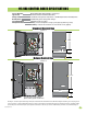
2.3 Limit Sensors Adjustment Continued 6004 Limit Switches ONLY Power to the circuit board must be ON when adjusting the limit sensors. D O O R K I N G Co ver A With operator cover removed, un-lock operator with Limit Switch Adjustment Note: Two thru-bolts 13 mm can be loosened to allow the electronic pallet to be moved around a little. Make sure ALL 4 limit switches make good contact with the 2 limit rings. release tool to release arm.
2.3 Limit Sensors Adjustment Continued 6400 Limit Sensors ONLY Power to the circuit board must be ON when adjusting the limit sensors. A With operator cover plate removed, un-lock release handle and pull handle to release gate. te 2 5338 VE H IC U LA R G AT E O PE R AT O R S TO RM L-325 TO . 247 NFO IED .2 NO CO ANSI/U HP TIF CER A C22 /CS CAN SS CLA DEL MO IAL SER LTS VO PS AM ASE PH Hz 60 , CA ood lew D , Ing E LOA Inc. X GAT rKing, MA Doo r ove Pla C le . ..
2.4 Inherent Reverse Sensor Adjustment This vehicular gate operator is equipped with an inherent (Built-In) adjustable reversing sensor (Type A) that is used as the primary entrapment sensing system according to the UL 325 standards. The gate will reverse direction upon encountering an obstruction in either the opening or closing gate cycle. For the reverse system to function correctly, the gate must be properly installed and work freely in both directions.
2.5 Shutdown Conditions Under various entrapment conditions the operator will assume either a SOFT or HARD (alarm) shutdown. To determine what type of reset action is required, you will need to understand how the different entrapment conditions affect the gate operator. Soft Shutdown This occurs in various situations where the inherent or secondary entrapment protection devices have been activated.
2.5 Shutdown Conditions Continued Hard Shutdown (Alarm Activated) A hard shutdown condition occurs when: (1.) The inherent entrapment protection system (Type A) gets activated TWO consecutive times before the gate completes the open or close cycle. (2.) The reversing edge (Type B2) gets activated and reverses but before the gate completes the reverse cycle the inherent entrapment protection system (Type A) gets activated.
SECTION 3 - MAINTENANCE AND TROUBLESHOOTING Inspection and service of this gate operator by a qualified technician should be performed anytime a malfunction is observed or suspected. High cycle usage may require more frequent service checks. 3.1 Maintenance When servicing the gate operator, always check any secondary (external) reversing devices (loops, photo sensors, etc.) for proper operation.
3.2 Diagnostics Check Continued 4. Check that there are no shorted or open control wires from the keying devices to the gate operator. If a keying device fails to open the gate, momentarily jumper across terminals 1 and 2 on the control board. If the gate operator starts, this indicates that a problem exist with the keying device and not with the gate operator. 5. Check the supply voltage and batteries.
3.3 Troubleshooting Continued Symptom Possible Solution(s) Gate starts to close, then reverses to open. • Disconnect the gate from the operator and check that the gate operates freely without any binding. • Check the loop detector LED’s and input LED’s. Any that flash ON will cause the gate to reverse. • If a shadow loop is used, check for proper wiring. A mis-wired shadow loop detector will cause the gate to reverse. • Continue troubleshooting or replace the circuit board.
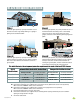
115 VAC Standard or Deluxe Control Box 12 V 3 Amp/Hr Battery Black Battery Plug 1 2 3 4 Black 12 Volt Battery Input 5 6 7 8 Alarm Reset Low Voltage Common 24 VAC Input 24 VAC Input + 1 2 3 4 5 6 7 Primary Operator Connector ONLY – Red 1 2 3 4 5 6 7 Secondary Operator Connector ONLY + – 12 V 3 Amp/Hr Battery 9 10 11 12 13 14 15 16 17 18 19 20 Black Red To #20 To #19 Red Red Red P/N 4302-112 P/N 4302-111 Standard Control Box Wiring Transformer Transformer Convenience Outlets 115
IMPORTANT INFORMATION FOR OWNER Shut-Off ALL Power to Operator OR Shut-Off Alarm Shut-Off ALL Power Turn OFF AC power switch AND carefully disconnect battery plug from circuit board to shut-off ALL power to operator. 1 2 3 4 5 6 7 4302 1 2 3 4 5 6 7 8 9 10 11 12 13 14 15 16 17 18 19 20 Shut-Off Alarm Standard Control Box Push button to SHUT-OFF alarm.
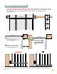
IMPORTANT INFORMATION FOR OWNER Manually Operating the Gate (NO Power) 6002 Manual Release ONLY ALL power to the operator must be OFF BEFORE manually operating gate (See previous page). Ac tua Arm OP EN OP EN 18 0° OP EN OP EN tor OP EN OP EN Co ver Insert allen wrench and turn 180° to release the arm. Push or pull the gate, NOT the actuator arm. Use key to unlock and remove the cover. Remove allen wrench from inside of cover.
4302-065-F-1-13 31
Wiring / Owner’s Manual 115 VAC Control Boxes for 6002, 6003, 6004 and 6400 gate operators Use this manual for circuit board 4302-010 Revision A or higher. 4302-065-F-1-13 www.doorking.com DoorKing, Inc. 120 Glasgow Avenue Inglewood, California 90301 U.S.A. Phone: 310-645-0023 Fax: 310-641-1586 Copyright 2009 DoorKing, Inc. All rights reserved.