
User guide

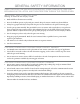
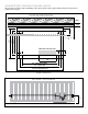
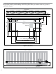
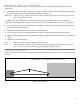
Table Of Contents
- IMPORTANT SAFETY INSTRUCTIONS
- Important Installation Instructions Ds4020/Ds 4020H/Ds & 4020HX (only)Gate operation
- Pad and Operator Location
- Important Installation Instructions for the DST 4520 0nly
- Gate operation
- Pad and Operator Location
- Concrete Pad Construction and Layout
- Operator Mounting
- Universal gate arm Installation Guidelines
- Arm Installation
- Initial Limit Adjustment
- Pipe Connection
- Dorene DGC2000 Controller
- Power Connection / Electrical Hookup115 Volt Single PhaseSee figure 10
- Mag-Lock installationIf a 115 volt lock is used, connect the neutral wire from the lock to port #7 and the power wire from thelock to port #6 
- Final Limit Adjustment
- DGC – 2000 Controller Settings 
- Hand
- Close Timer
- Reverse Delay 
- Close Delay 
- Motor Run Timer 
- Sensitivity Adjustment 
- Warning Alarm 
- To Hold Gate Open
- JP-3 
- Led enable switch 
- Final Assembly
- Blue Box formatAll Commands are dry contact, except JS4 & JS8
- JS1
- JS2
- JS3
- JS4
- JS5
- JS6
- JS7
- JS8
- JS9
- JS10
- Jp3
- Jp4
- Shadow loop Installation
- SychronousOPEN/CLOSE OPERATIONDGC 2000
- Double Swing gate loop placement
- 
- Final Check
- Maintenance
- Safety Accessories
- Installation
- Testing
- Warning
- Caution
- Troubleshooting
- The left LED’S
- The Right LED’s
- Gate will not open or operate
4
INSTALL THE GATE OPERATOR ONLY WHEN:
e operator is appropriate for the construction of the gate and the usage class of the gate.1.
All openings of a horizontal slide gate are guarded or screened from the bottom of the gate to a2.
Minimum of 4’ (1.2m) above the ground to prevent a 2.25” (57.15mm) diameter sphere from passing 3.
through the openings anywhere in the gate, and in that portion of the adjacent fence that the gate
covers in the open position.
All exposed pinch points are eliminated or guarded4.
Guarding is supplied for exposed rollers 5.
e operator is intended for installation only on gates used for vehicles. Pedestrians must be supplied
with a separate access opening.
e gate must be installed in a location so that enough clearance is supplied between the gate and
adjacent structures when opening and closing to reduce the risk of entrapment. Swinging gates shall
not open into public access areas.
e gate must be properly installed and work freely in both directions prior to the installation of the gate
operator. Do not over-tighten the operator clutch or pressure relief valve to compensate for a damaged gate
For gate operator utilizing type D protection 6.
e gate operator controls must be placed so that the user has full view of the gate area when the gate 7.
is moving. e placard as required by 52a.1.6 shall be placed adjacent to the controls
An automatic closing device (such as a timer, loop sensor, or similar device) shall not be employed. 8.
No other activation device shall be connected.
Controls must be far enough from the gate so that the user is prevented from coming in contact with the 9.
gate while operating the controls. Controls intended to be used to reset an operator aer two sequential
activations of the entrapment protection device or devices must be located in the line-of-sight of the gate.
All warning signs and placards must be installed where visible in the area of the gate.