
User guide
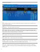
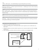
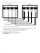
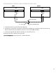
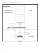
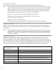


Table Of Contents
- IMPORTANT SAFETY INSTRUCTIONS
- Important Installation Instructions Ds4020/Ds 4020H/Ds & 4020HX (only)Gate operation
- Pad and Operator Location
- Important Installation Instructions for the DST 4520 0nly
- Gate operation
- Pad and Operator Location
- Concrete Pad Construction and Layout
- Operator Mounting
- Universal gate arm Installation Guidelines
- Arm Installation
- Initial Limit Adjustment
- Pipe Connection
- Dorene DGC2000 Controller
- Power Connection / Electrical Hookup115 Volt Single PhaseSee figure 10
- Mag-Lock installationIf a 115 volt lock is used, connect the neutral wire from the lock to port #7 and the power wire from thelock to port #6 
- Final Limit Adjustment
- DGC – 2000 Controller Settings 
- Hand
- Close Timer
- Reverse Delay 
- Close Delay 
- Motor Run Timer 
- Sensitivity Adjustment 
- Warning Alarm 
- To Hold Gate Open
- JP-3 
- Led enable switch 
- Final Assembly
- Blue Box formatAll Commands are dry contact, except JS4 & JS8
- JS1
- JS2
- JS3
- JS4
- JS5
- JS6
- JS7
- JS8
- JS9
- JS10
- Jp3
- Jp4
- Shadow loop Installation
- SychronousOPEN/CLOSE OPERATIONDGC 2000
- Double Swing gate loop placement
- 
- Final Check
- Maintenance
- Safety Accessories
- Installation
- Testing
- Warning
- Caution
- Troubleshooting
- The left LED’S
- The Right LED’s
- Gate will not open or operate

22
TROUBLESHOOTING
To trouble shoot the gate operator it is important to understand how the LED’s function work.
Note: The power LED functions all the time that power get to the DGC 2000 Controller box. The LED’s
function for thirty minutes from power-up and go off automatically to save power. To verify that the
LED’s are enabled, activate a limit switch momentarily. If the corresponding LED does not light,
press the LED enable switch, located below the LED’s to enable them for another thirty minutes.
Troubleshooting Assumes the following: (which are not necessarily true):
There is 115v AC power to L-1 and neutral at the high voltage terminal.
The LED’s have been enabled (press the LED enable switch if necessary)
All external controls are connected.
There are no loose or “bad” connections.
IfanLEDisindicatingapossiblecausetothemalfunction,thatproblemisdealtwithrst.
THE LEFT LED’S
OPEN, CLOSE, STOP, PULSE O/C, SAFETY indicate what external inputs are being activated. If the gate is
stuck open or closed, rst verify that one of those LED’s is not on, indicating that an accessory is holding it in
that position.
Note: TheSTOPLEDwillcontinuouslyashthreetimesandpauseafterthemotorhasrunlongertheset-
ting on the motor run timer. The operator will not function again until power has been removed and
re-applied. It is important to determine the cause of this and correct the problem before putting the
unit back into operation.
THE RIGHT LED’S
OPEN LIMIT, CLOSE LIMIT, CLOSE TIMER, OPEN MODE, and CLOSE Mode indicate what operator
functions are taking place. e OVER CURRENT LED lights when the current sensor activates and stays on
until another input of action takes place. is LED can also light if no current is sensed for 15 seconds while the
motor is “being told” to run. Also if, for example, the OPEN LIMIT LED is lit while the open limit switch is not
activated, check for a defective switch. Flashing OVER CURRENT LED indicated low voltage situation.
GATE WILL NOT OPEN
OR OPERATE
No LED’s are on
Cause Solution
No power between L1 and
Neutral with power switch on
Check connection from power supply
Check wiring from high voltage terminal to power plug. Replace as necessary
If problem can’t be corrected, you may need to replace the controller
No power between L-1 and
Neutral with power switch o
Check connection from high voltage plug to controller
Check wiring from high voltage terminal to power plug. Replace as necessary.