
User guide
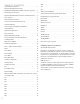
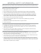
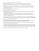
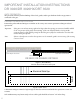
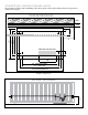
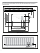
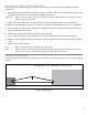
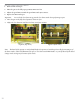
Table Of Contents
- IMPORTANT SAFETY INSTRUCTIONS
- Important Installation Instructions Ds4020/Ds 4020H/Ds & 4020HX (only)Gate operation
- Pad and Operator Location
- Important Installation Instructions for the DST 4520 0nly
- Gate operation
- Pad and Operator Location
- Concrete Pad Construction and Layout
- Operator Mounting
- Universal gate arm Installation Guidelines
- Arm Installation
- Initial Limit Adjustment
- Pipe Connection
- Dorene DGC2000 Controller
- Power Connection / Electrical Hookup115 Volt Single PhaseSee figure 10
- Mag-Lock installationIf a 115 volt lock is used, connect the neutral wire from the lock to port #7 and the power wire from thelock to port #6 
- Final Limit Adjustment
- DGC – 2000 Controller Settings 
- Hand
- Close Timer
- Reverse Delay 
- Close Delay 
- Motor Run Timer 
- Sensitivity Adjustment 
- Warning Alarm 
- To Hold Gate Open
- JP-3 
- Led enable switch 
- Final Assembly
- Blue Box formatAll Commands are dry contact, except JS4 & JS8
- JS1
- JS2
- JS3
- JS4
- JS5
- JS6
- JS7
- JS8
- JS9
- JS10
- Jp3
- Jp4
- Shadow loop Installation
- SychronousOPEN/CLOSE OPERATIONDGC 2000
- Double Swing gate loop placement
- 
- Final Check
- Maintenance
- Safety Accessories
- Installation
- Testing
- Warning
- Caution
- Troubleshooting
- The left LED’S
- The Right LED’s
- Gate will not open or operate
2
TABLE OF CONTENTS
General Safety Instructions ............................3
Important Installation Instructions
DS4020/DS 4020H/DS & 4020HX (only) Gate operation ....6
Pad and Operator Location ............................6
Important Installation Instructions for the DST 4520 0nly ....8
Gate operation ......................................8
Pad and Operator Location ............................8
Concrete Pad Construction and Layout . . . . . . . . . . . . . . . . . . 9
Operator Mounting . . . . . . . . . . . . . . . . . . . . . . . . . . . . . . . . . . 9
Universal gate arm Installation Guidelines ...............10
Arm Installation . . . . . . . . . . . . . . . . . . . . . . . . . . . . . . . . . . . 10
Initial Limit Adjustment . . . . . . . . . . . . . . . . . . . . . . . . . . . . . 11
Pipe Connection . . . . . . . . . . . . . . . . . . . . . . . . . . . . . . . . . . . 11
Dorene DGC2000 Controller . . . . . . . . . . . . . . . . . . . . . . . . . 12
Power Connection / Electrical Hookup115
Volt Single Phase . . . . . . . . . . . . . . . . . . . . . . . . . . . . . . . . . . 12
Mag-Lock installation ..............................13
Final Limit Adjustment ..............................14
DGC – 2000 Controller Settings .......................14
Hand . . . . . . . . . . . . . . . . . . . . . . . . . . . . . . . . . . . . . . . . . . . . 14
Close Timer .......................................14
Reverse Delay .....................................14
Close Delay .......................................15
Motor Run Timer . . . . . . . . . . . . . . . . . . . . . . . . . . . . . . . . . . 15
Sensitivity Adjustment . . . . . . . . . . . . . . . . . . . . . . . . . . . . . . 15
Warning Alarm . . . . . . . . . . . . . . . . . . . . . . . . . . . . . . . . . . . . 15
To Hold Gate Open . . . . . . . . . . . . . . . . . . . . . . . . . . . . . . . . 16
JP-3 .............................................16
Led enable switch ..................................16
Final Assembly . . . . . . . . . . . . . . . . . . . . . . . . . . . . . . . . . . . . 16
Blue Box (DGC 2000 ) format All Commands are dry contact,
except JS4 & JS8 .............................. 17
JS1 ..............................................17
JS2 ..............................................17
JS3 ..............................................17
JS4 ..............................................17
JS5 ..............................................17
JS6 ..............................................17
JS7 ..............................................17
JS8 ..............................................18
JS9 ..............................................18
JS10 .............................................18
Jp3 ..............................................18
Jp4 ..............................................18
Shadow loop Installation .............................18
Synchronous Open/Close Operation DGC 2000 . . . . . . . . . . 19
Double Swing gate loop placement . . . . . . . . . . . . . . . . . . . . 21
Final Check .......................................22
Maintenance . . . . . . . . . . . . . . . . . . . . . . . . . . . . . . . . . . . . . . 22
Safety Accessories . . . . . . . . . . . . . . . . . . . . . . . . . . . . . . . . . 22
Installation ........................................22
Testing ...........................................22
Warning .......................................... 22
Caution . . . . . . . . . . . . . . . . . . . . . . . . . . . . . . . . . . . . . . . . . . 22
Troubleshooting . . . . . . . . . . . . . . . . . . . . . . . . . . . . . . . . . . . 23
The left LED’S . . . . . . . . . . . . . . . . . . . . . . . . . . . . . . . . . . . . 23
The Right LED’s ................................... 23
Gate will not open or operate . . . . . . . . . . . . . . . . . . . . . . . . . 23
LIMITED WARRANTY SUMMARY
(For Normal Wear and Tear)
DoreneL.L.C warrants all gate openers to be free of defects in
material & workmanship for a period of 4 years for commercial
use and 6 years for residential use, i.e. single residence, from date
of purchase. Any mechanical part or parts found defective within
this period, at the manufacturer’s option, shall be repaired or
replaced free of charge.
FOB our factory.
The above warranty is in lieu of all other warranties expressed
or implied and shall be void in cases of acts of God, vandalism,
improper installation or improper maintenance.
The electronics are warranted for a period of 2 years under the
same requirements.