
User guide
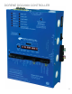
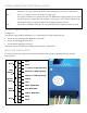
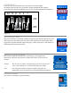
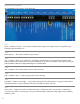
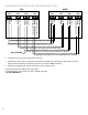
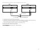
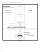
Table Of Contents
- IMPORTANT SAFETY INSTRUCTIONS
- Important Installation Instructions Ds4020/Ds 4020H/Ds & 4020HX (only)Gate operation
- Pad and Operator Location
- Important Installation Instructions for the DST 4520 0nly
- Gate operation
- Pad and Operator Location
- Concrete Pad Construction and Layout
- Operator Mounting
- Universal gate arm Installation Guidelines
- Arm Installation
- Initial Limit Adjustment
- Pipe Connection
- Dorene DGC2000 Controller
- Power Connection / Electrical Hookup115 Volt Single PhaseSee figure 10
- Mag-Lock installationIf a 115 volt lock is used, connect the neutral wire from the lock to port #7 and the power wire from thelock to port #6 
- Final Limit Adjustment
- DGC – 2000 Controller Settings 
- Hand
- Close Timer
- Reverse Delay 
- Close Delay 
- Motor Run Timer 
- Sensitivity Adjustment 
- Warning Alarm 
- To Hold Gate Open
- JP-3 
- Led enable switch 
- Final Assembly
- Blue Box formatAll Commands are dry contact, except JS4 & JS8
- JS1
- JS2
- JS3
- JS4
- JS5
- JS6
- JS7
- JS8
- JS9
- JS10
- Jp3
- Jp4
- Shadow loop Installation
- SychronousOPEN/CLOSE OPERATIONDGC 2000
- Double Swing gate loop placement
- 
- Final Check
- Maintenance
- Safety Accessories
- Installation
- Testing
- Warning
- Caution
- Troubleshooting
- The left LED’S
- The Right LED’s
- Gate will not open or operate

19
SYNCHRONOUS OPEN/CLOSE OPERATION DGC 2000
STOP
COMMON
PULSE
RED
BLACK
RED
BLACK
JS7
STOP
COMMON
PULSE
JS7
LEFT RIGHT
RED STOP WIRES
BLACK COMMON WIRESN.C. SWITCH
Controllers must be operated from same 110v line.1.
Synchronous* Open/Close operation ins obtained by installing two twisted pair cables between the JS1 2.
Open/Common and Close/Common connectors of two DGC 2000 controllers.
Connection required only with the Gate Edge or other Safety Device.3.
*Formerly referred to as Master-Slave Operation
Twisted pair cable - Belden P/N 9501