
User guide
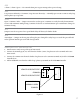
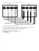
Table Of Contents
- IMPORTANT SAFETY INSTRUCTIONS
- Important Installation Instructions Ds4020/Ds 4020H/Ds & 4020HX (only)Gate operation
- Pad and Operator Location
- Important Installation Instructions for the DST 4520 0nly
- Gate operation
- Pad and Operator Location
- Concrete Pad Construction and Layout
- Operator Mounting
- Universal gate arm Installation Guidelines
- Arm Installation
- Initial Limit Adjustment
- Pipe Connection
- Dorene DGC2000 Controller
- Power Connection / Electrical Hookup115 Volt Single PhaseSee figure 10
- Mag-Lock installationIf a 115 volt lock is used, connect the neutral wire from the lock to port #7 and the power wire from thelock to port #6 
- Final Limit Adjustment
- DGC – 2000 Controller Settings 
- Hand
- Close Timer
- Reverse Delay 
- Close Delay 
- Motor Run Timer 
- Sensitivity Adjustment 
- Warning Alarm 
- To Hold Gate Open
- JP-3 
- Led enable switch 
- Final Assembly
- Blue Box formatAll Commands are dry contact, except JS4 & JS8
- JS1
- JS2
- JS3
- JS4
- JS5
- JS6
- JS7
- JS8
- JS9
- JS10
- Jp3
- Jp4
- Shadow loop Installation
- SychronousOPEN/CLOSE OPERATIONDGC 2000
- Double Swing gate loop placement
- 
- Final Check
- Maintenance
- Safety Accessories
- Installation
- Testing
- Warning
- Caution
- Troubleshooting
- The left LED’S
- The Right LED’s
- Gate will not open or operate

15
TO HOLD GATE OPEN
Wire switch to stop prior to full open to close reverse switch and press transmitter to restart.
JP-3
Anti-tailgate feature. See Figure #6 on page 11
LED ENABLE SWITCH
e two rows of LED’s, located in the upper le hand corner of the
DGC 3000, Functions for thirty minutes from power-up and turns o
automatically to save power. To verify the LED’s are enabled, activate a limit
switch momentarily. If the corresponding LED does not light, press the
LED enable button, located below the 2 rows of LED’s, to turn on the LED’s
for another 30 minutes.
Safety is for secondary entrapment – devices connected to this terminal will cause the gate to stop and
reverse 3”. e gate must be activated by a person to move aer this has occurred.
Pulse Open/Pulse Close terminal is used to both open and close the gate from a single button. Activation of the
button will open the gate unless the gate is fully open in which case it will close the gate.
24V Power terminal is one leg of 24 VAC power (COMMON is the other side of 24 VAC power, and is
grounded), which can be used to power a radio receiver, digital keypad or other accessory with 24 VAC voltage
requirements.
Important: This terminal must not be grounded at any time even through any controls which will be used to
activate the gate!
FINAL ASSEMBLY
Operate the gate to the middle of its operation and turn power OFF at the breaker (this prevents activation of 1.
the operator during nal assembly). If preferred, you may turn power OFF and back ON at the operator, the
operator will not move until activated.
Remove the arm by removing the stainless steel bolt.2.
Install the operator cover (make sure the grommet remains properly seated), and re-install the arm as 3.
described under ARM INSTALLATION.
Tighten the stainless steel bolt to 44./lbs.4.
e gate operator installation is not complete unless the warning signs are installed on the gate.5.