
User guide
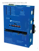
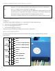
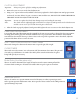
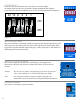
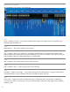
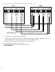
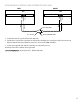
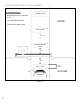
Table Of Contents
- IMPORTANT SAFETY INSTRUCTIONS
- Important Installation Instructions Ds4020/Ds 4020H/Ds & 4020HX (only)Gate operation
- Pad and Operator Location
- Important Installation Instructions for the DST 4520 0nly
- Gate operation
- Pad and Operator Location
- Concrete Pad Construction and Layout
- Operator Mounting
- Universal gate arm Installation Guidelines
- Arm Installation
- Initial Limit Adjustment
- Pipe Connection
- Dorene DGC2000 Controller
- Power Connection / Electrical Hookup115 Volt Single PhaseSee figure 10
- Mag-Lock installationIf a 115 volt lock is used, connect the neutral wire from the lock to port #7 and the power wire from thelock to port #6 
- Final Limit Adjustment
- DGC – 2000 Controller Settings 
- Hand
- Close Timer
- Reverse Delay 
- Close Delay 
- Motor Run Timer 
- Sensitivity Adjustment 
- Warning Alarm 
- To Hold Gate Open
- JP-3 
- Led enable switch 
- Final Assembly
- Blue Box formatAll Commands are dry contact, except JS4 & JS8
- JS1
- JS2
- JS3
- JS4
- JS5
- JS6
- JS7
- JS8
- JS9
- JS10
- Jp3
- Jp4
- Shadow loop Installation
- SychronousOPEN/CLOSE OPERATIONDGC 2000
- Double Swing gate loop placement
- 
- Final Check
- Maintenance
- Safety Accessories
- Installation
- Testing
- Warning
- Caution
- Troubleshooting
- The left LED’S
- The Right LED’s
- Gate will not open or operate
12
POWER CONNECTION / ELECTRICAL HOOKUP
Important: Turn power OFF at the breaker before making any connections or adjustments.
Note: Port 1, 2, 11 and 12 are not to used. ey are empty ports.
e operator should be on a separate line with a 15 AMP breaker. Supply voltage must be within
10% of the operator rating under load conditions. Connect power in accordance with local codes
All operations must be properly grounded with a supply grounding conductor
Note: Master Slave installations must have the same phase power when separate breakers are used
115 VOLT SINGLE PHASE
See gure 11
#12 OR #14 gauge shielded, standard wire is recommended for the high voltage hoop-ups.
Secure the 115 volt single phase HOT line to port #101.
Secure ground supply line to port #92.
Secure neutral supply line to port #83.
Important: Turn power OFF before making any connections or adjustments.
MAG-LOCK INSTALLATION
If a 115 volt lock is used, connect the neutral wire from the lock to port #7 and the power wire from the
lock to port #6
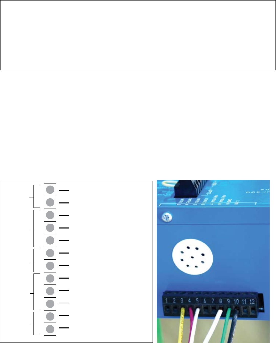
1
Dead
Dead
Dead
L-1 (hot) (117 VAC) input only
High
Voltage
In
Mag Lock
Wires
Motor
Wires
Neutral (117 VAC) input only
Ground (117 VAC) input only
Neutral
Lock
White - Motor Wire
Red - Motor Wire
Yellow - Motor Wire
Dead
2
3
4
5
6
7
8
9
10
11
12
Dead
Dead
Figure 11 (Power Connection)