
User guide

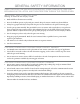

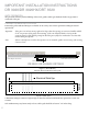
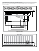
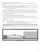
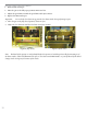
Table Of Contents
- IMPORTANT SAFETY INSTRUCTIONS
- Important Installation Instructions Ds4020/Ds 4020H/Ds & 4020HX (only)Gate operation
- Pad and Operator Location
- Important Installation Instructions for the DST 4520 0nly
- Gate operation
- Pad and Operator Location
- Concrete Pad Construction and Layout
- Operator Mounting
- Universal gate arm Installation Guidelines
- Arm Installation
- Initial Limit Adjustment
- Pipe Connection
- Dorene DGC2000 Controller
- Power Connection / Electrical Hookup115 Volt Single PhaseSee figure 10
- Mag-Lock installationIf a 115 volt lock is used, connect the neutral wire from the lock to port #7 and the power wire from thelock to port #6 
- Final Limit Adjustment
- DGC – 2000 Controller Settings 
- Hand
- Close Timer
- Reverse Delay 
- Close Delay 
- Motor Run Timer 
- Sensitivity Adjustment 
- Warning Alarm 
- To Hold Gate Open
- JP-3 
- Led enable switch 
- Final Assembly
- Blue Box formatAll Commands are dry contact, except JS4 & JS8
- JS1
- JS2
- JS3
- JS4
- JS5
- JS6
- JS7
- JS8
- JS9
- JS10
- Jp3
- Jp4
- Shadow loop Installation
- SychronousOPEN/CLOSE OPERATIONDGC 2000
- Double Swing gate loop placement
- 
- Final Check
- Maintenance
- Safety Accessories
- Installation
- Testing
- Warning
- Caution
- Troubleshooting
- The left LED’S
- The Right LED’s
- Gate will not open or operate
10
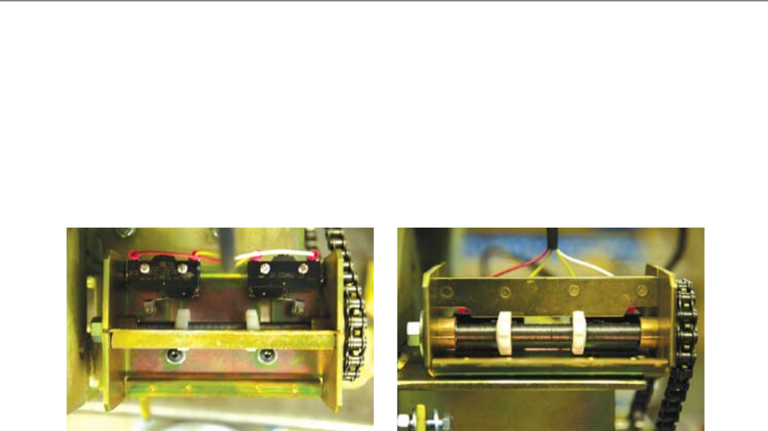
INITIAL LIMIT ADJUSTMENT
Remove limit nut keeper1.
Move the gate to the fully open position, minus one foot2.
Adjust the open limit nut until the open limit switch just activates.3.
Replace the limit nut keeper.4.
Important: Do not let the close limit nut go past the close limit switch when performing step #5.
Move the gate to the fully closed position, minus one foot5.
Adjust the close limit nut until the close limit switch just activates.6.
Figure 8 (Top View) Figure 9 (Side View)
Note: e hand of the operator is easily identied aer the operator is hooked up electrically by activating on of
the limit switches, which will illuminate the open or close limit switch LED. Hand is very easily altered by the hand
change switch. See Fig #7 for location of the switch.