Model 1550ETL–1K Single Swing Gate Operator Model 1650ETL-1K Dual Swing Gate Operator INSTALLATION MANUAL Rev 11.
Table of contents IMPORTANT SAFETY INSTRUCTIONS …………………………………………………………...II APPLICATION ….……………………………………………………………………………………… III PRE-INSTALLATION CHECKLIST …………………………………...…………………..…….….. IV PART IDENTIFICATION ………………………………………...……………………………………….. V Optional parts identification 1. OPERATOR INSTALLATION ………………………………………………………..………… 7 1.1 - Pivot Arm Installation (standard pull to open) 1.2 - Actuator Installation 1.3 - Control Box Installation 1.4 - Apollo 816-1K limit switch and smart sensor wiring 1.
IMPORTANT SAFETY INSTRUCTIONS WARNING - To reduce the risk of injury or death: x x x x x x READ AND FOLLOW ALL INSTRUCTIONS. Installation should be performed by a professional installer. Required welding should be performed by a qualified welder. Should electricity be required, use a certified electrician only. Any device that requires 120 Volts AC should be U.L. approved.
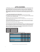
APPLICATIONS The Apollo Model 1550ETL-1K/1650ETL-1K Swing Gate Operator is approved for Vehicular Class I & II usage under UL 325 Guidelines, and is designed to handle swing gates up to 16 feet in length and 600 pounds each. A professional fence or gate dealer is recommended to assure proper installation. Apollo Gate Operators are available only through qualified dealers with an outstanding reputation in the fence and gate industry.
PRE-INSTALLATION CHECKLIST The following check list should be used before beginning installation: Verify that the proper operator has been selected for this application. Verify proper installation and operation of the gate. 1. Are the hinges servicable? 2. Does the gate swing free and level? 3. Will the gate require a locking device? 4. Is the hinge and stop posts sturdy enough to handle the gate & operator? 5. Does the gate meet U.L.
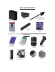
PART IDENTIFICATION Part# 816E Actuator with 8’ cable (816EX slave actuator with 38’ cable supplied with 1650 Part# 10025215 Gate Bracket (2 with 1650) Part# 11111B - CONTROL BOX Part# 1116 Pivot Arm (2 with 1650) Part# 1125 Hardware Kit (2with 1650) Part# 273 - CAUTION Sign (2 each) (4 each with 1650) OPTIONS Part# 201 5 Watt Solar Panel & Bracket (2 required with 1650) Part# OVIEW Part# 320N Nice Transmitter Part# 404C Automatic Battery Charger Part# FT210B V6 Part#: MOFB Part# 446 Bolt On Piv
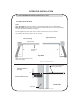
OPERATOR INSTALLATION 1.1 - PIVOT ARM INSTALLATION (standard pull to open) Location of Pivot Point. Notes: PULL TO OPEN pulls gate open (actuator is extended when gate is in the closed position). PUSH TO OPEN pushes the gate open (actuator is retracted when gate is in the closed position). For PUSH TO OPEN installations see page 11. If a 400 Upgrade Kit is to be used, refer to the 400 instructions for pivot point location. The following instructions provide up to 105o of swing.
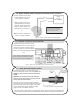
IMPORTANT Never weld parts to the gate or posts when the operator circuit board is powered. Doing so may damage the board beyond repair. 1.2 - Actuator Installation 1/2” x 3 1/2” Hex Bolt 1/2” Washer Do not over tighten Nut and Bolt 1/2” Lock Nut Figure 3: Actuator Installation 1.3 - Control Box Installation Mount the control box within 4 feet of the pivot arm. Do not mount the control box where the person using the push button on side of the box can come in contact with the gate.
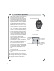
1.5 - Apollo actuator motor wiring and connection to the controller Connect the Apollo 816-1K actuator motor leads to the 3-pin connector as shown in Figure 6. Apollo 816-1K Red and Black Red black Note: If the gate moves in the opposite direction from what is expected, reverse the actuator wiring from what is shown in the figure (Red to Pin 1, Black to Pin 3). Note - If gate moves in opposite direction from what is expected, reverse the motor power lead wiring.
1.8 - Limit Switch Adjustment 1. Install all gate accessories such as Photo-Eye’s, Sensors, Loops and other safety devices. 2. Apply battery power to the 1050 gate operator. 3. Remove the limit switch screw end caps from the Apollo 816-1K Series actuator. See Figure 8 Apollo 816-1K Series Limit Screw Adjustment. 4. Test the motor direction by pressing CLOSE. If the gate instead OPENS swap the RED and BLACK motor leads shown in Figure 7 and retest to verify correct operation. 5.
PUSH TO OPEN INSTALLATION 2.1 - PIVOT ARM(s) INSTALLATION Location of pivot point Direction of opening Hinge post Gate (closed) Both measurements are taken from the center of the hinge. 6” Top View 11” Figure 11: Pivot Arm Top View Center Line of attachment point for gate bracket Vertical position of pivot arm (s) 1/2” Pivot arm must be level Front View Hinge Figure 12: Pivot Arm Front View 2.
3 - CIRCUIT BOARD LAYOUT Figure 15 - CONTROL BOARD BUTTONS Figure 16 - CIRCUIT BOARD LAYOUT 12
4 - OUTPUTS & INPUTS Commercial Gate Operator Accessory Outputs: OUT1 and OUT2: Individual, isolated relays provide COMMON, NORMALLY OPEN, and NORMALLY CLOSED dry contacts for switching accessories based on programming of the “Auxiliary IO” function. These outputs are programmed in the “FUNCTION Auxiliary I/O” menu. Magnetic Lock: Provides fused power (1.85A max) and isolated relay COMMON, NORMALLY OPEN, and NORMALLY CLOSED dry contacts for electrically powered and maintained magnetic locks.
4.1 - Gate Operator Accessory Inputs (Continued) Guard Station Open: (34) Dry contact input for a guard station open switch. Momentarily shorting the digital input to GND opens the gate to the full open position with the subsequent auto-close feature enabled. Guard Station Stop: (35) Dry contact input (Normally Closed) for a guard station stop switch. Momentarily opening this input stops the opening gate at its current position.
4.2.2 - Programming the plug-in receiver and remote controls SMXI/A Plugin Receiver: The SMXI/A 433Plug-In Receiver provides up to 15 channels for specific control of individual gate functions. The receiver includes built-in programming functions for adding or removing Nice FloR/A wireless remote controls to/from a gate installation.
4.2.3 - OVIEW REMOTE CONTROL OVIEW (see page 6 for Picture of OVIEW) Programming and diagnostic unit which connects directly to the gate controller and is part of the Nice “Opera” control system. The unit can be used in “stand-alone” mode via its front-panel keypad, or it may be accessed via a Bluetooth or cellular-enabled PDA, PC, or Smartphone when used with the O-View Software Suite.
6 - OPTIONAL INPUTS/OUTPUTS 6.1 - Fire dept. connection 32 FIRE 33 GND Dry contact input for a fire department control switch. Normally Open (NO) contact must be shorted to ground through a switch to open the gate. Figure 20 - FIRE DEPT. INPUT 6.2 - Exit and edge inputs wiring diagram 28 EDGE 29 GND 30 EXIT 31 GND The EDGE input may be configured as a monitored ANALOG input, or DIGITAL (NC or NO) input.
6.4 - Magnetic lock connection 7 NC 8 Com (Common) 9 NO 10 GND 11 V+ This connection is used to install the magnetic lock. In this instance a gate can be locked magnetically to prevent a forced opening. Consult lock manual for specifics on installation and wiring. Note: Terminal 11 voltage is equal to system input voltage. Figure 23 - MAGNETIC LOCK WIRING (EXAMPLE) 6.
8 - GENERAL LAYOUT AND SAFETY ACCESS Figure 25 - LAYOUT FOR IN-GROUND LOOPS Figure 26 - LAYOUT FOR PHOTOCELLS 19
9 - ACCESSORIES AND SENSORS EXTERNAL ENTRAPMENT PROTECTION: Non-contact and contact sensors must be installed individually or in combination with each other to provide external entrapment protection. Care should be exercised to reduce the risk of nuisance tripping, such as when a vehicle trips the sensor while the gate is still moving, and one or more non-contact sensors shall be located where the risk of entrapment or obstruction exists, such as the perimeter reachable by a moving gate or barrier.
10 - BOARD DIAGRAM Figure 27 - GENERAL BOARD OVERVIEW THE PROGRAMMING BUTTONS INDICATED IN THE ABOVE REFERENCE SHOULD BE USED ONLY AFTER UNDERSTANDING THE MANUAL AND ITS RELATION TO THE PROGRAMMING SEQUENCES SHOWN ON THE FOLLOWING PAGES. CARE SHOULD BE TAKEN WHENEVER CHANGES ARE IMPLEMENTED TO ENSURE PROPER FUNCTIONALITY AND SAFETY.
11 - PROGRAMMING BUTTONS 11.1 - Force Static: Set sensitivity to constant force on a scale of 1 to 10 (1 being the most sensitive). Dynamic: Set sensitivity of sudden impact force to the moving gate on a scale of 1 to 10 (1 being most sensitive). ESC: Exit the FORCE menu. 11.2 - Speed Max: Sets the limit of maximum allowed gate speed on a scale of 20% to 100% (20% being the lowest setting).
11.5 - Function Learn: Puts the gate operator into learning mode for a Swing or Slide gate and Blue BUS peripherals. Learning mode for a Swing or Slide style gate involves selecting the gate type (Light, Average, Heavy), then fully opening and closing the gate to sense the limits. Selecting the gate type selects precalculated values for the FORCE, SPEED, and ACCELERATION settings.
11.5 - Function (continued) Radio Channel: For the Plug-in Onboard Receiver, 15 radio channels may be programmed with one of the following options: • No program • OPEN (Default CH. 2) • CLOSE • STEP (Default CH. 1) • PARTIAL • PARTIAL 1 • STOP • HOLD TO OPEN • HOLD TO CLOSE • TIMER 1 • TIMER 2 • LOCK • UNLOCK • OPEN and LOCK • CLOSE and LOCK • OPEN and UNLOCK • CLOSE and UNLOCK • STEP H • TOGLE and LATCH Timers: Set time for count down timers Timer 1 and Timer 2.
11.5 - Function (Continued) Timer (continued) To program weekly events EV1 through EV8, perform the following steps: 1. Press FUNCTION -> Events. 2. Press and hold OK to display EV1 (display will blink “EV1”). 3. Press UP or DOWN to toggle between events, then press OK to make a selection. The display changes to hours. 4. Press UP or DOWN to toggle between hours, then press OK to make a selection. The display changes to minutes. 5.
11.5 - FuncƟon (ConƟnued) Advance Settings: The following settings are available for customizing the gate operator as required by the customer’s installation requirements: x Set Language (English, Spanish, Italian) x Set clock 12H/24H x Set LCD Contrast x Direction of the Motor (only selectable in learning mode) x Auto Close Opt. (ON - Gate only closes when at open limit, OFF - Gate auto-closes from any open position) x Exit Opt.
11.6 - Display ESC: Exit the DISPLAY menu. Info: Displays the manufacturer name, product name/model, software versions, and serial number. Clock: Displays the calendar date and time in the real time clock. Pressing and holding the “OK” button for 5 seconds enables the date and time settings to be updated manually. Main Volt: Displays the gate operator main control voltage in volts DC. Battery Volt: Displays the gate operator backup battery voltage in volts DC.
12 - GLOSSARY (Continued) CLASS IV - RESTRICTED ACCESS VEHICULAR GATE OPERATOR - A vehicular gate operator (or system) intended for use in a guarded industrial location or building such as an airport security area or other restricted access locations not servicing the general public, in which unauthorized access is prevented via supervision by security personnel. LOCK- Ceases all operator function except HIGH PRIORITY inputs.
14 - MAINTENANCE SCHEDULE - APOLLO GATE OPENER TABLE 2 COMPLETE BASIC Alarm Active the primary (inherent) reverse system by blocking the gate with a solid object. The gate should reverse momentarily then stop. Restart the gate and Lock again with a solid object. The gate should reverse momentarily, then stop, and go into hard shutdown with an alarm ● ● Battery Check the batteries for any leakage or loose connections.
16 - APOLLO 816-1K PROGRAMMING QUICK START Learning 816-1K actuator 1. Connect battery power to board. 2. Install all gate accessories such as Photo-Eye’s, Sensors, Loops and other safety devices. 3. Remove the limit switch screw end caps from the Apollo 816-1K Series actuator. See section 1.8 Apollo 816-1K Series Limit Screw Adjustment. 4. Test the motor direction by pressing CLOSE. If the gate instead OPENS swap the RED and BLACK motor leads shown in Figure 7 and retest to verify correct operation. 5.
18 - INSTALLATION CHECKLIST Left box is for installer check off and the right box is for customer check off. 1. The gate has been checked to make sure it is level and moves freely in both directions. 2. Potential pinch areas have been guarded so as to be inaccessible OR have contact and/or non-contact obstruction sensing devices installed. 3. The installer has installed one or more contact or non-contact obstruction sensing devices, in compliance with UL325 requirements for this installation. 4.
LIMITED TWO-YEAR WARRANTY Apollo Gate Operators are warranted against defects for a period of 24 months from the date of purchase, providing recommended installation procedures are followed.