
User guide


1150-065-F-1-11
17
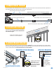
2.7 Loop Detector Wiring
Loop detectors must be installed to prevent the gate from accidentally closing on vehicles that may be in the path of the gate.
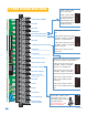
• Install 9410-101 Single Channel or 9409-101 Dual Channel DoorKing plug-in loop detectors (Sold separately).
• If using external loop detectors, use only UL listed (or equivalent) detectors. Use a separate power supply for
external loop detectors. Inputs to circuit board are Normally Open (NO).
• Disconnect power to gate operator before installing any loop detectors.
LIMIT
LIMIT
PA RT
TIME
DELAY
REV SENSE
CLOSE
REV SENSE
OPEN
1
ON
2 3 41
ON
2 3 4 5 6 7 8
NO NC
EXIT
LOOP
REVERSE
LOOP
GATE FORCED
20
19
18
17
16
15
14
13
12
11
10
9
8
7
6
5
4
3
2
1
9410
9410
External Loop Connections
Normally Open
Reverse Loop
Automatic Exit Loop
Reverse Loop
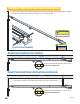
• Loop layout shown is for a typical overhead gate application
with two-way traffic, or one-way exit only traffic.
• Refer to the Loop Information Manual (available from
www.dkaccess.com) for more information on loops and
loop detectors.
Automatic exit loop
lead in wires are
twisted approx. 6
twists per foot.
Reverse loop lead in wires are twisted approx.
6 twists per foot and are wired in series.