
User guide


1150-065-F-1-11
13
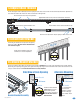
Chassis Ground
ON/OFF Power Switch
Neutral - White
Hot - Black
High Voltage Conduit
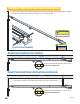
2.2 High Voltage Wire Run
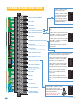
2.3 High Voltage Terminal Connection
The distance shown in the chart is measured in Feet from the operator to the power source. If power wiring is greater than
the maximum distance shown, it is recommended that a service feeder be installed. When large gauge wire is used, a
separate junction box must be installed for the operator connection. The wire table is based on stranded copper wire. Wire
run calculations are based on a 110 VAC power source with a 3% voltage drop on the power line, plus an additional 10%
reduction in distance to allow for other losses in the system.
• Route incoming high voltage power through conduit and into the operator as shown.
• Be sure wiring is installed in accordance with local codes. Be sure to color code all wiring.
• Connect power wires as shown.
• It is recommended that a surge suppressor be installed on the high voltage power lines to help
protect the operator and circuit board from surges and power fluctuations.
Never run high voltage and low voltage wires in the same conduit. Keep them in separate conduits.
This table illustrates the high voltage wire size and distance requirements.
Model
Type
Voltage
Required
Amps
Required
Wire Size / Distance in Feet
115 5.4 170 275 460 685
12 AWG 10 AWG 8 AWG 6 AWG
1150
LIMIT
LIMIT
PA RT
TIME
DELAY
REV SENSE
CLOSE
REV SENSE
OPEN
1
ON
2 3 41
ON
2 3 4 5 6 7 8
NO NC
EXIT
LOOP
REVERSE
LOOP
GATE FORCED
DANGER
HIGH VOLTAGE!
PUSH TO OPERATE
technician use only