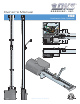
Owner’s Manual Overhead Gate Operator 1150 EXIT LOOP LIMIT LIMIT PART technician use only PUSH TO OPERATE 1 2 3 4 1 2 3 4 5 6 7 8 ON TIME DELAY REV SENSE CLOSE GATE FORCED REV SENSE OPEN ON REVERSE LOOP NO NC Copyright 2011 DoorKing, Inc. All rights reserved.
SPECIFICATIONS Dimension A Class of Operation Type of Gate Horsepower/ Voltage / Phase Current Max Gate Dimensions Gear Reduction Chain Type Cycles Per Hour Speed Entrapment Protection Model 1150 - UL325 Class II, III and IV Vehicular high traffic overhead gates only. ½ HP - 115 VAC - 60 Hz. Single-Phase 5.4 Amps Height - 14 Feet, Width - 25 Feet 40:1 Worm gear in a continuous oil bath.
TABLE OF CONTENTS SPECIFICATIONS Overhead Gate Protection Gate Construction Important Safety Instructions Instructions regarding intended installation: Important Notices UL325 Entrapment Protection Glossary SECTION 1 - INSTALLATION 1.1 1.2 1.3 1.4 1.5 1.6 Attach Rails to Powerhead Manual Release and Chain Connection Adjust Chain Tension Attach Gate Bracket Attach Header Bracket Mount Powerhead and Finish Installation SECTION 2 - WIRING 2.1 2.2 2.3 2.4 2.5 2.6 2.
Overhead Gate Protection Reverse Loop C Minimizes the potential of the gate closing when a vehicle is present. Placement of loops is dependent on the application. B C A Reverse Loop Minimizes the potential of the gate closing when a vehicle is present. Placement of loops is dependent on the application. Separate Pedestrian Walkway Located so pedestrians cannot come in contact with the vehicular gate.
Gate Construction Vehicular gates should be constructed and installed in accordance with ASTM F2200; Standard Specification for Automated Vehicular Gate Construction. For a copy of this standard, contact ASTM directly at 610-832-9585; service@astm.org; or www.astm.org. Important Safety Instructions WARNING - To reduce the risk of injury or death: 1. READ AND FOLLOW ALL INSTRUCTIONS. 2. Never let children operate or play with gate controls. Keep the remote control away from children. 3.
• For gate operators utilizing contact sensors: 1. One or more contact sensors shall be located where the risk of entrapment or obstruction exist, such as at the leading edge, trailing edge, and post mounted both inside and outside of a vehicular horizontal slide gate. 2. One or more contact sensors shall be located at the bottom edge of a vehicular vertical lift gate. 3. One or more contact sensors shall be located at the pinch point of a vehicular vertical pivot gate. 4.
UL325 Entrapment Protection Class I Class II A vehicular gate operator (or system) intended for use in a home of one-to four single family dwelling, or a garage or parking area associated therewith. A vehicular gate operator (or system) intended for use in a commercial location or building such as a multi-family housing unit (five or more single family units) hotel, garages, retail store or other building servicing the general public.
Glossary GATE - A moving barrier such as a swinging, sliding, raising, lowering, or the like, barrier, that is a stand-alone passage barrier or is that portion of a wall or fence system that controls entrance and/or egress by persons or vehicles and completes the perimeter of a defined area. RESIDENTIAL VEHICULAR GATE OPERATOR – CLASS I - A vehicular gate operator (or system) intended for use in a home of one-to four single family dwelling, or garage or parking area associated therewith.
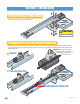
SECTION 1 - INSTALLATION 1.1 Attach Rails to Powerhead Secure rails with 4 bolts, nuts and lock washers. CAUTION FRAGILE POWERHEAD! 1.2 Manual Release and Chain Connection Cut wire ties and route chain around gear reducer’s sprocket and through unlocked carriage assembly (To unlock assembly, use key to unlock release ring, pull ring up and rotate 45° to release spring loaded chain catch). Connect chain together with double master link.
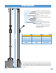
1.3 Adjust Chain Tension Do not overtighten chain. Make adjustments equally on both sides of rails. Chain will need final adjustment after operator has been mounted. Chain will stretch over time and will need to be tightened. Do not let chain touch steel rail separators. Approximate chain tension, front rail removed for illustration. LIMIT LIMIT PART EXIT LOOP REVERSE LOOP Chain must be centered between rails. Return wheel must be centered between rails.
1.6 Mount Powerhead and Finish Installation Connect rails to header bracket. The powerhead must be protected from damage. Use the shipping box and packing material to set the powerhead on while connecting the rails to the header bracket. CAUTION FRAGILE POWERHEAD! Packing Material Header Bracket Assembly SHIPPING BOX Mount Powerhead Directly to Ceiling Ceiling Install the powerhead with lag bolts or anchor sleeves.
Connect Carriage Arm Carriage assembly must to be unlocked. After connecting the arm, manually raise and lower the gate, be sure the gate is operating smoothly and is not binding anywhere. Any interference must be corrected now. Fill Mark IMPORTANT: The carriage assembly’s spring loaded chain catch will only lock into place in the double master chain link. Final Chain Adjustment Install Breather Cap in Gearbox Install breather cap after operator has been mounted.
SECTION 2 - WIRING Before attempting to connect any wiring to the operator, be sure that the circuit breaker in the electrical panel is in the OFF position. Permanent wiring must be installed to the operator as required by local electrical codes. It is recommended that a licensed electrical contractor perform this work.
2.2 High Voltage Wire Run The distance shown in the chart is measured in Feet from the operator to the power source. If power wiring is greater than the maximum distance shown, it is recommended that a service feeder be installed. When large gauge wire is used, a separate junction box must be installed for the operator connection. The wire table is based on stranded copper wire.
2.4 Main Terminal Description 2. NOT USED 6 7 8 9 6. NOT USED ON 2 3 4 5 4 SW 1 3. NOT USED • When gate is closed, this input will open gate. 4. OPEN INPUT/ EXIT LOOP LOGIC OUTPUT 7. STANDARD REVERSE/STOP INPUT 8. OPEN INPUT DoorKing 3-Button Control Station Only • When gate is open and auto close timer SW 1, switch 2 is turned ON, input will re-set and hold timer. • When gate is open and auto close timer SW 1, switch 2 is turned OFF, input will close gate. ON 5 5.
2.5 Control Wiring Controls must be installed far enough from the gate so that the user is prevented from coming in contact with the gate while operating the controls. Use 18 AWG wire for all low voltage wiring, maximum distance 3000 feet. Use a low voltage surge suppressor, DoorKing P/N 1878-010 if low voltage wire runs exceed 1000 feet. All inputs to the main terminal must be Normally Open (NO). Telephone Entry Note: All stand-alone and telephone entry devices must use a separate power source.
2.6 Secondary Entrapment Protection Wiring Secondary entrapment prevention devices must be installed to insure a safe operating environment and reduce the risk of personnel entrapment. Secondary entrapment prevention may be provided by a combination of both type sensors (UL 325 Type B1 and B2). • Use only UL listed (or equivalent) sensors. • Sensors shall be located where the risk of entrapment or obstruction exists, such as the perimeter reachable by a moving gate or barrier.
2.7 Loop Detector Wiring Loop detectors must be installed to prevent the gate from accidentally closing on vehicles that may be in the path of the gate. 1 2 3 4 9410 ON LIMIT LIMIT PART 1 2 3 4 5 6 7 8 EXIT LOOP ON Automatic exit loop lead in wires are twisted approx. 6 twists per foot.
SECTION 3 - ADJUSTMENTS The switch settings and adjustments in this chapter should be made after your installation and wiring to the operator is complete. Whenever any of the programming switches on the circuit board are changed, power must be shut-off, and then turned back on for the new setting to take effect. 3.1 Circuit Board Adjustments CAUTION SW 1 ON 1 2 3 4 Do not run self-test with the operator connected to the gate. The drive chain must be disconnected from the operator to run the self-test.
3.2 DIP-Switch Descriptions and Functions The two DIP-switches located on the circuit board are used to program the operator to operate in various modes and to turn on or off various operating features. Whenever a switch setting is changed, power to the operator must be turned OFF and then turned back on for the new setting to take affect. Check and review ALL switch settings prior to applying power to the operator.
3.3 Limit Switch Adjustments Basic DIP Settings ON 1 2 3 4 5 6 7 8 • Start-up direction should be ON. SW 1, switch 1. • Auto close timer (when turned on) SW 1, switch 2. • SW 1, switch 3 should be ON. SW 1 ON 1 2 3 4 • SW 2, switch 3 should be ON. SW 2 Setting Timer Adjust from 1 second (full counter clockwise) to approximately 23 seconds (full clockwise). 1 23 • Turn power off. • Push and hold locking plate tab. • Adjust limit nuts at full open and full close gate positions.
3.4 Inherent Reverse Sensors Adjustment This vehicular gate operator is equipped with an inherent (Type A) entrapment sensing system. This system will sense an obstruction in either the opening or closing gate cycles and will cause the gate to reverse direction should an obstruction be encountered. For this system to function correctly, the gate must be properly installed and work freely in both directions.
SECTION 4 - TECHNICAL INSTRUCTIONS Inspection and service of this gate operator by a qualified technician should be performed anytime a malfunction is observed or suspected. High cycle usage may require more frequent service checks. 4.1 Maintenance When servicing the gate operator, always check any secondary (external) reversing devices (loops, photo eyes, etc.) for proper operation.
A malfunction in a loop or loop detector can cause the gate operator to hold open, or not detect a vehicle when it is present over the loop. Pull the loop detector circuit boards from the loop ports on the operator circuit board. If the malfunction persists, the problem is not with the loop system. For more information refer to the loop detector instruction sheet and the DoorKing Loop and Loop Detector Information Manual.
Symptom Possible Solution(s) Continued from previous page. If the motor runs in both steps from previous page, replace the control board. If the motor does not run, or runs in only one direction, problem can be a bad motor, motor capacitor, wire connections from the control board to the motor or a bad control board. Gate opens but will not close. Gate closes but will not open. • SW-2, switch 3 may be set incorrectly. Be sure that this switch is in the ON position for overhead gate operation.
4.4 Accessories The following accessory items are available for the model 1150 overhead gate operator. Contact Sensors - For use as a secondary entrapment protection device. Miller Edge, Inc., ME120, ME123, MGO20, MGR20, MGS20. Photo Cell - Non-contact (photo-cells) sensors for use as a secondary entrapment protection device. P/N 8080-010 – Infrared thru-beam, 165 foot sensing distance. P/N 8080-011 – Photo-reflective beam, 30 foot sensing distance.
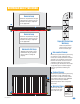
1150 Wiring Schematic Com Blue Yellow NO NO PUSH TO OPERATE technician use only CLOS OPEN E Brown Com 12345 1 2 3 4 5 6 7 8 1 2 3 4 ON LIMIT LIMIT PART ON EXIT LOOP 1 2 3 4 5 6 7 8 9 TIME DELAY REV SENSE OPEN 10 11 12 REV SENSE CLOSE NO NC REVERSE LOOP GATE FORCED 13 14 15 16 17 18 19 Red Blue 1/2 HP Single Phase 20 Ground NEU HOT 115 VAC Neutral Hot Chassis Ground AC ON/OFF Power 26 1150-065-F-1-11
Owner’s Manual 1150 Overhead Gate Operator DoorKing, Inc. 120 Glasgow Avenue Inglewood, California 90301 U.S.A. Phone: 310-645-0023 Fax: 310-641-1586 1150-065-F-1-11 www.doorking.