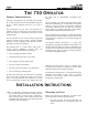
June, 2004 750 Operator And 455 D Control Pa nel Installation Manual THE 750 OPERATOR AND 455 D CONTROL PANEL: INSTALLATION MANUAL Important Safety Information 2 Technical Data 4 Unpacking the Operator 5 The 750 Operator General Characteristics 6 Installation Instructions 6 Prepare the Gate 6 Installing the 750 Operator 7 Set the Concrete Forms 7 Install the Power Unit 8 Install the Drive Unit 9 Install the Hydraulic Lines 10 Synchronize the Hydraulic System 10 Install the Gate Leaf
June, 2004 750 Operator And 455 D Control Pa nel Installation Manual Page 2 I M PORTANT S AFE TY I NFORM ATION Both the installer and the owner and/or operator of this system need to read and understand this installation manual and the safety instructions supplied with other components of the gate system. This information should be retained by the owner and/or operator of the gate. WARNING! To reduce the risk of injury or death 1. READ AND I N S T R U C T IO N S . 2.
J une, 2004 750 Operat or And 455 D Control Pa nel Installation Manual P a ge 3 USE 1. 2. 3. Use this equipment only in the capacity for which it was designed. Any use other than that stated should be considered improper and therefore dangerous. When using any electrical equipment, observe some fundamental rules: • Do not touch the equipment with damp or humid hands or feet. • Do not install or operate the equipment with bare feet. • Do not allow small children or incapable persons to use the equipment.
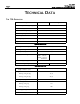
June, 2004 750 Operator And 455 D Control Pa nel Installation Manual P age 4 TECHNICAL DATA THE 750 OPERATOR Description 750 Standard Ambient temperature, deg F (deg C) 750 Long Leaf -13 to 158 (-25 to 70) Maximum duty cycle 30 Cycles/ Hour Thermal cut out, deg F (deg C) 212 (100) Power voltage required, VAC 115 ±10% or 230, +6 or -10%, 60 Hz Absorbed power, W 220 Motor speed, rpm 1400 Type of oil FAAC HD (Aeroshell 41) Hydraulic Power Unit: Height × width × depth, in.
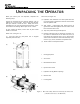
J une, 2004 750 Operat or And 455 D Control Pa nel Installation Manual UNPACKING P a ge 5 THE When you receive your 750 Operator, complete the following steps: Inspect the shipping box for physical damage such as leaking oil or a torn carton. Then inspect the operator after you remove it from the box. Notify the carrier immediately if you note any damage because the carrier must witness the damage before you can file a claim.
J une, 2004 750 Operator And 455 D Control Pa nel Instal lation Manual P age 6 THE 750 OPERATOR GENERAL CHARACTERISTICS The FAAC 750 Operator is an automatic gate operator for a swinging gate leaf. It can accommodate a gate leaf of up to 1760 lb (800 kg) and up to 13 ft (4 m) in length. The 750 Operator is a two piece unit consisting of a hydraulic power (or pump) unit and a hydraulic ram (or drive) unit which are connected by the means of two hydraulic hoses.
J une, 2004 750 Operat or And 455 D Control Pa nel Installation Manual P a ge 7 2. The distance between the gate post and the center of the gate hinge must be at least 2 3/8 in. (6 cm). SET THE CONCRETE FORMS You need to lay out the concrete forms according to the dimensions shown in Figures 3 and 4. (Your soil conditions will also determine the size of the cement footing.) 3. Make sure the gate leaf has positive stops in both the opening and closing directions (see Figure 3).
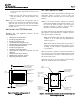
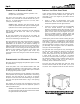
June, 2004 750 Operator And 455 D Control Pa nel Installation Manual P age 8 INSTALL THE POWER UNIT Figure 5 shows important dimensions and parts of the vinyl power unit box. There are two constraints to installing the power unit box for the 750 Operator: 1. We recommend that you install the power unit box so that the hydraulic lines between it and the drive unit are no longer than 20 ft (6 m). 2.
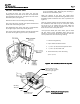
J une, 2004 750 Operat or And 455 D Control Pa nel Installation Manual P a ge 9 INSTALL THE DRIVE UNIT To install the drive unit, first make sure the four leveling bolts on the base of the unit do not protrude from the bottom of the unit. Then place the unit on the foundation plate (see Figure 6). Position the drive unit according to the following: The side of the drive unit with the splined shaft should be the side nearest the gate post.
June, 2004 750 Operator And 455 D Control Pa nel Installation Manual P a ge 1 0 CONNECT THE HYDRAULIC LINES Caution: It is important that the hydraulic lines be kept clean of any debris. The drive unit and power unit are connected by two hydraulic lines, each with an outside diameter of 5/16 in. (0.8 cm), an inside diameter of 5/32 in. (0.4 cm), and a 2,500 psi (170 bar) rating.
J une, 2004 750 Operat or And 455 D Control Pa nel Installation Manual P a ge 1 1 Next you need to position the sleeve for the splined shaft of the pinion (or the shear-pin assembly) on the bottom side of the U-shaped section of the shoe as shown in Figure 9. On the bottom of the U-shaped shoe section, center the sleeve around the pilot hole that marks the axis or rotation. Accurately centering the pilot hole is important.
June, 2004 750 Operator And 455 D Control Pa nel Installation Manual P a ge 1 2 Absolute minimum of 5 in. (12.7 cm) between vertical section and end of U-shaped section Vertical section can be located on either side of axis of rotation Figure 10. Top view of the U-shaped section of the gate leaf shoe. Centerline of gate leaf Axis of rotation for gate leaf Thickness of the gate leaf Bottom of U-shaped section Minimum of 3/4 in. (1.9 cm) Recommended minimum of 10 in.
J une, 2004 750 Operat or And 455 D Control Pa nel Installation Manual P a ge 1 3 D C E A F B Locate Activation Devices at least 10 ft from the gate Gate System Parts 1 2 3 4 5 6 750 hydraulic drive unit 750 hydraulic power unit 750 Control Panel box Main power switch Circuit breaker Main junction box 7 8 9 Switch for 750 Operator Switch for 750 Operator Radio receiver Figure 11.
P a ge 1 4 With the hydraulic system disengaged, open the gate leaf by hand to a half-opened position. Re-engage the hydraulic system. If you have a CBAC model of the 750 Operator (with hydraulic locking in the fully opened and fully closed positions), then first try to move the gate leaf. If you are unable to make the gate leaf move, then you do not need to bleed the hydraulic system.
J une, 2004 750 Operat or And 455 D Control Pa nel Installation Manual P a ge 1 5 Extension Arm With Positive Stops Attaches to the bottom of the gate Side View Slides through side channel as gate swings Top View 750/ 760 collar Positive stops (not included) Positive Stops Figure 12.
P a ge 1 6 June, 2004 750 Operator And 455 D Control Pa nel Installation Manual 750 OPERATOR
J une, 2004 750 Operat or And 455 D Control Pa nel Installation Manual P a ge 1 7 750 PARTS LIST POS PART NO. DESCRIPTION QTY POS 1 N/A Bolt (10mm x 25mm) 2 2 N/A Lock washer 3 7091045 4 PART NO. DESCRIPTION 21 N/A Bolt (8mm x 100mm) 2 22 N/A Lock Washer Piston Ring 2 23** 7366235 Cylinder (100 degree) 2 7350155 Piston 2 24 N/A O-Ring (66.4 mm x 1.78 mm) 2 5* 7193055 750 Rack (100 degree) 1 25 7170275 Flange (Right Side) 1 6 N/A O-Ring (26.70mm x 1.
P a ge 1 8 June, 2004 750 Operator And 455 D Control Pa nel Installation Manual 750 CBAC OPERATOR
J une, 2004 750 Operat or And 455 D Control Pa nel Installation Manual P a ge 1 9 750 CBAC PARTS LIST POS PART NO. DESCRIPTION QTY POS PART NO. DESCRIPTION 1 3204385 Lobe Pump (.75 Lt) 1 2* 3 77000425 115 V 1400 RPM Motor 7514125 Electric Power Cord 4 7099315 5 28 2274 Allen Bolt (4mm x 6mm) 1 1 29 4180225 Manual Release 1 1 30 7090050015 O-Ring (10.82mm x 1.
June, 2004 750 Operator And 455 D Control Pa nel Installation Manual P a ge 2 0 750 PUMP ENCLOSURE POS PART NO. DESCRIPTION QTY 1 N/A Self-tapping screw (3.9mm x 9.5mm) 1 2 N/A Washer 1 3 N/A Snap Ring 1 4 N/A O-Ring (15.6mm x 1.78mm) 1 5 7128035 Lock Body (Enclosure) 1 6 713002 Triangular Release Key 1 7 N/A Galvanized Self-tapping Screw (2.9mm x 9.5mm) 1 8 7309105 Plastic Hinge 2 9 720309 750 Enclosure 1 10 N/A Self-tapping Screw (4.8mm x 16.
J une, 2004 750 Operat or And 455 D Control Pa nel Installation Manual P a ge 2 1 750 FLEX HOSE CONNECTOR KIT PROCEEDURES FOR INSTALLING FLEX-HOSE TO COPPER ADAPTER LEGEND Note: The parts are shown in proper installation order. A Flexible Hydraulic Hose B Flex-hose to Compression Adapter (2-Piece) C Flex-hose to Compression Adapter (2-Piece) D Compression Nut E Ferrule Fitting 1. Screw item B onto the hydraulic hose A (counter clock-wise) until tight. 2. Screw item C into item B & A.
June, 2004 750 Operator And 455 D Control Pa nel Installation Manual THE 455 D CONTROL PANEL INSTALLATION INSTRUCTIONS P age 2 2 THE 455 D CONTROL PANEL GENERAL DESCRIPTION The FAAC 455 D control panel is used to operate the following models. NOTE: An installation is U.L. compliant only when you install the FAAC operators according to the UL325 standards.
J une, 2004 750 Operat or And 455 D Control Pa nel Installation Manual In order to wire motor 2 in a bi-parting system, connect the white wire to terminal 4 (on the J4 terminal strip), the black wire to 5, the red wire to 6. Wire each leg of the capacitor (supplied) to terminals 5 & 6. TO THE WARNING! Turn the main power off before you make any electrical connections or before programming.
June, 2004 750 Operator And 455 D Control Pa nel Installation Manual N 22 23 24 25 L 1 2 3 4 5 6 COM OP CL COM OP CL 115 VAC +/- 10% or 230 VAC +6/ -10% 50-60 Hz C1 M1 7 8 9 10 11 12 13 14 15 16 17 18 19 CL OP LAMP - - - FSW MOTOR 2 BLUE MOTOR 1 BLUE THE 455 D CONTROL PANEL INSTALLATION INSTRUCTIONS P a ge 2 4 + + 24V FSW 20 21 W.LIGHT LOCK ELECTRIC LOCK C2 FOR WHEN THE FAAC GATECODERS ARE USED 24 vdc 3W M2 OPEN Figure 2-CP.
J une, 2004 750 Operat or And 455 D Control Pa nel Installation Manual (b) To the U. L. Listed gate operator U.L. Listed U.L. Listed Control Panel Enclosure 455 MPS Control Panel Junction box cord grip High-voltage Legend Figure 3-CP. Wiring detail (a) inside the junction box and (b) from the junction box or operator to the highvoltage terminal strip on the 455 D control panel terminal strip White J3 Red Black Yellow/ J4 J1 COM OP CL COM OP CL Green To the U.L.
June, 2004 750 Operator And 455 D Control Pa nel Installation Manual THE 455 D CONTROL PANEL INSTALLATION INSTRUCTIONS P a ge 2 6 devices for opening and closing, safeties are triggered. Use the LEDs and the table in Figure 4-CP to determine if the accessory devices you have installed are operating properly. Electric Locks: An electric lock can be wired to the 455 D in terminals 18 and 21 (12Vac pulsed provided).
J une, 2004 750 Operat or And 455 D Control Pa nel Installation Manual P a ge 2 7 + Lock 17 9 NO 14 14 C 18 12 vac Relay N.C. N.O. 21 COM Shadow Loop FAAC Rev ersing Photocells (f or opening) Additional Reversing Devices 1 TX 2 19 17 C 12 NC Coil Voltage = Motor Voltage Additional Reversing Devices 1 13 19 N.C. 2 14 N.O.
June, 2004 750 Operator And 455 D Control Pa nel Installation Manual THE 455 D CONTROL PANEL INSTALLATION INSTRUCTIONS P a ge 2 8 PROGRAMMING BASIC PROGRAMMING To program the automated system, “Programming Mode” must be accessed. Programming is split into two parts: ADVANCED. the F BASIC and Display BASIC PROGRAMMING To access BASIC PROGRAMMING, press the “F” key. • If you press it (and hold it down), the display shows the name of the first function.
J une, 2004 750 Operat or And 455 D Control Pa nel Installation Manual P a ge 2 9 Display Function Default MAXIMUM TORQUE AT INITIAL THRUST: The motors operate at maximum torque (ignoring the torque setting) at start of movement. Useful for heavy leaves. Y = Enable No = Disabled LAST STROKE AT CLOSING: The motors are activated at full speed for 1s to facilitate locking of the electric lock.
June, 2004 750 Operator And 455 D Control Pa nel Installation Manual THE 455 D CONTROL PANEL INSTALLATION INSTRUCTIONS P a ge 3 0 LEARNING OF OPERATING TIMES WARNING: During the learning procedure, the safety devices are disabled! Therefore, any and all traffic must be avoided in the path of the gate leaf(s). and 14, or radio control): • • NOTE: Programming must start with the gate(s) in the closed position.
J une, 2004 750 Operat or And 455 D Control Pa nel Installation Manual • COMPLETE LEARNING NOTES: • • • If only one gate operator (1) is used, you must go through the entire programming procedure, as if you were programming a gate operator (2). When the gate operator (1) has finished opening, supply 5 open commands until the gate operator begins to close, and then resume normal operations.
June, 2004 750 Operator And 455 D Control Pa nel Installation Manual P a ge 3 2 THE 455 D CONTROL PANEL INSTALLATION INSTRUCTIONS A (Automatic) Logic (455 D) Gate Status Open A Open B Stop Opening Reversing Device(s) Closing Reversing Device(s) Warning Light Closed Opens both leaves and closes them after pause time Opens single leaf connected to Motor 1 and closes it after pause time No effect No effect No effect Off No effect On Opening No effect No effect Stops Stops; gate closes wh
J une, 2004 750 Operat or And 455 D Control Pa nel Installation Manual P a ge 3 3 E (Semi-automatic) Logic (455 D) Open A Open B Stop Opening Reversing Device(s) Closing Reversing Device(s) Warning Light Closed Opens both leaves Opens single leaf connected to Motor 1 No effect No effect No effect Off Opening Stops Stops Stops Stops; gate closes when reversing device no longer triggered No effect On Opened Closes both leaves Closes leaf Stops No effect No effect (opening is inhibit
June, 2004 750 Operator And 455 D Control Pa nel Installation Manual P a ge 3 4 MAINTENANCE THE 750 OPERATOR The FAAC recommended maintenance schedule varies according to the frequency of use of the operators, whether lightly used operators (once or twice an hour) or heavily used operators (many cycles per hour). Check the oil. To check the oil level correctly, remove the oil filler cap on the top of the power unit.
J une, 2004 750 Operat or And 455 D Control Pa nel Installation Manual SAFETY • • • • • P a ge 3 5 IN GATE DESIGN • Pedestrians should not use a vehicular gate system. Prevent such inappropriate use by installing separate gates for pedestrians. • The operating controls for an automatic gate must be secured to prevent the unauthorized use of those controls.
J une, 2004 750 Operator And 455 D Control Pa nel Instal lation Manual P a ge 3 6 TROUBLESHOOTING WARNING! Before you do any work on the control panel, be sure to turn off the main power. NOTE: Any control panel specific information in the following applies to the 455 D control panel only. Problem: The gate does not respond to an activating signal. Solution: Verify that you have correctly wired the operator to the control panel. Verify that the LED DL3 is on.
J une, 2004 750 Operat or And 455 D Control Pa nel Installation Manual P a ge 3 7 TROUBLESHOOTING WARNING! Before you do any work on the control panel, be sure to turn off the main power. NOTE: Any control panel specific information in the following applies to the 455 D control panel only. Check to see that there are no obstructions in the path of the gate or that the hinges are not binding. Problem: The operator doesn't work smoothly and the gate jerks as it opens and closes.
J une, 2004 750 Operator And 455 D Control Pa nel Ins tallation Manual P a ge 3 8 OPERATOR LOCATION WHEN USING THE EXTENSION ARMS WITH STOPS Outside of Property Gate Post 750 Splined Shaft 20-1/2" Grade 2" 3-3/4" minimum To increase this distance, add material between splined collar and extension arm.
June, 2004 750 Operator And 455 D Control Pa nel Installat ion Manual P a ge 3 9 This page left blank intentionally.
J une, 2004 750 Operat or And 455 D Control Pa nel Installation Manual P a ge 4 0 LIMITED WARRANTY To the original purchaser only: FAAC International, Inc., warrants, for twenty-four (24) months from the date of invoice, the gate operator systems and other related systems and equipment manufactured by FAAC S.p.A. and distributed by FAAC International, Inc.