
User guide

Limit Switches wiring in-
structions:
Limit switches are wired in the
same terminal block where
the motor wiring has been in-
stalled. Wire the limit switches
as follows:
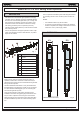
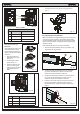
1. Open the second pre-
drilled hole in the cover,
see Fig. 15.
2. Fit the supplied cable
gland, see Fig. 15.
3. Insert the cable and con-
nect it to the terminals,
following the connections
specied in Figure 16
Table.
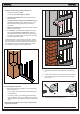
• Close and secure the cover with the four supplied screws
(Fig. 17).
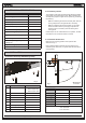
4.6 Adjusting the Limit Switches
Note: Limit switches are triggered during the rst and the last
1.25 inches of travel. Therefore, the operator should utilize
the entire available length of travel during the opening phase.
Shorter travels can limit or completely cancel the limit switch
adjustment range.
Limit switches adjustment is carried out as follows:
1. Unscrew the upper fastening screw, Fig.18 Ref.A, and
remove the cap, Fig.18 Ref.B.
2. To adjust the closing limit switch FCC, turn the adjust-
ing screw clockwise (Fig.19 Ref.A) to increase rod
stroke and counter-clockwise to reduce it.
3. To adjust the opening limit switch FCA, turn the adjust-
ing screw counter-clockwise (Fig. 20 Ref. A) to in-
crease rod stroke and clockwise to reduce it.
4. Perform a pair of test cycles to check the correct posi-
tion of the limit switch. If the limit switch needs ad-
ditional adjustment, repeat the operation starting from
Step 2.
10
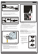
FAAC Model 415 L LS 24V Swing Gate Operator
Fig. 14
Figure 14 Table
415 (24 VDC)
POS. COLOR DESCRIPTION
1 White Motor Lead 1
- Not used -
2 Brown Motor Lead 2
Fig. 15
Fig. 16
Figure 16 Table
POS. COLOR DESCRIPTION
1 Blue Common
2 Brown Closing Limit Switch (FCC)
3 Black Opening Limit Switch (FCA)
Fig. 18
Fig. 19
Fig. 17