415 L LS 24V Swing Gate Operator UL325 - UL991 FAAC International Inc. Headquarter & East Coast Operations 5151 Sunbeam Road Suites 9-11 Jacksonville, FL 32257 Tel. 866 925 3222 www.faacusa.com FAAC International Inc. West Coast Operations 357 South Acacia Avenue Unit 357 Fullerton, CA 92831 Tel.
CONTENTS IMPORTANT SAFETY INFORMATION 3 Important Safety Instructions Important Installation Instructions General Safety Precautions UL325 Gate Operator Classifications Installing the Warning Signs 3 3 4 5 5 1. DESCRIPTION 6 2. DIMENSIONS 6 3. TECHNICAL SPECIFICATIONS 7 4. INSTALLATION 7 4.1 Electrical Set-up (Standard System) 4.2 Preliminary Checks 4.3 Installation Dimensions 4.4 Installing the Operator 4.5 Wiring the Operator 4.6 Adjusting the Limit Switches 4.7.
IMPORTANT SAFETY INFORMATION Important Safety Instructions WARNING: TO REDUCE THE RISK OF SEVERE INJURY OR DEATH: • READ AND FOLLOW ALL INSTRUCTIONS. • Never let children operate or play with the gate controls. Keep remote controls away from children. • Always keep people and objects away from the gate. NO ONE SHOULD CROSS THE PATH OF A MOVING GATE. • Test the gate operator monthly. The gate MUST reverse on contact with a rigid object or when an object activates a non-contact sensor.
General Safety Precautions Important Installation Instructions (continued) 9. For gate operators that utilize a contact sensor (edge sensor or similar): • Locate one or more contact sensors where the risk of entrapment or obstruction exists, such as at the leading edge, trailing edge, and post mounted both inside and outside of a vehicular horizontal slide gate • Locate one or more contact sensors at the bottom edge of a vehicular vertical lift gate.
UL325 Gate Operator Classifications RESIDENTIAL VEHICULAR GATE OPERATOR CLASS I A vehicular gate operator system intended for use in a single family dwelling, garage or associated parking area. COMMERCIAL / GENERAL ACCESS VEHICULAR GATE OPERATOR CLASS II A vehicular gate operator system intended for use in commercial locations or buildings such as multi-family housing units (five or more single family units), hotels, parking garages, retail stores or other buildings that service the general public.
M o d e l 4 1 5 L L S 2 4 V Swin g Ga t e Op e ra t o r 1. DESCRIPTION The FAAC 415 is an automatic gate operator for swinging gate leafs. The 415 Operator is useful in residential applications and can accommodate gate leafs up to 14 ft long. The self-contained 415 Operator consists of an electric motor that drives a worm screw housed in an aluminum casing. The locking provided by the 415 Operator (in the fully opened and fully closed positions) is a service device rather than a security device.
3. TECHNICAL SPECIFICATIONS SPECIFICATION 415 L LS 24V Power Supply 24 VDC Power (W) 70 Current (A) 3 Thrust (lbf) 630 Effective Stroke (inches) 15 Rod Extension Speed (inches/sec) 0.5 Max Leaf Length (feet) 15 Cycle per hour at 68˚F (approx) 75 Class or Operation Residential Ambient Operating Temperature Range (˚F) -4 to +131 Operator Weight (lbs) 17.5 Protection Class IP 54 4. 4.
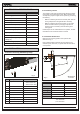
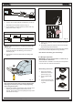
Guidelines for Determining Installation Dimensions • For 90° leaf openings: A+B=L • For leaf openings exceeding 90°: A+B
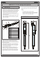
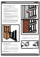
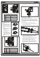
Fig. 9 6. Turn the rod one half revolution clockwise (Fig. 9, Ref. 2). 7. Assemble the front bracket as shown in Fig. 10. 8. Fix the operator to the rear bracket by means of the supplied pins as shown in Fig. 11. Fig. 12 Fig. 10 12. Perform the necessary corrective measures and repeat from Step 11. Attention: allow the bracket to cool before fastening the operator to it. 13. Temporarily release the operator from the front bracket and permenantly weld the bracket. 9.
• Close and secure the cover with the four supplied screws (Fig. 17). Fig. 14 Figure 14 Table 415 (24 VDC) POS. COLOR Fig. 17 DESCRIPTION 1 White Motor Lead 1 - Not used - 2 Brown Motor Lead 2 4.6 Adjusting the Limit Switches Note: Limit switches are triggered during the first and the last 1.25 inches of travel. Therefore, the operator should utilize the entire available length of travel during the opening phase.
Fig. 21 Ref. 2 Fig. 20 5. Fig. 21 Ref. 3 Reposition the cap (Fig. 18 Ref. B) and tighten the fastening screw (Fig. 18 Ref. A). 4.7. Start-up ATTENTION: Cut power before performing any work on the system or operator. Carefully observe the GENERAL SAFETY RULES. Following the indications in Fig. 3, lay the proper cable conduits and make the electrical connections of the control board and chosen accessories. 1.
8. POS. P/N DESCRIPTION POS. P/N DESCRIPTION 01 72200165 REAR MOUNTING BRACKET 18 718367 SCREW DRIVE PIN WITH SEEGER 02 72840065 REAR MOUNTING PLATE 19 499399 LOCKING LOWER FLANGE 20 N/A 6.3X19mm SELF TAPPING SCREW 21 60202225 GEAR (piston) 22 N/A 4.
1. E024U CONTROL BOARD DESCRIPTION & CHARACTERISTICS J24 + SETTING DL14 DL15 DL16 DL17 DL18 DL19 DL20 DL21 DL22 Fig. A1 1.1 TECHNICAL SPECIFICATIONS 1.2 LAYOUT AND COMPONENTS Main power supply 115/230 V~ 50/60 Hz switchable Secondary power supply Power consumption 24 Vdc - 16 A max. (min. 20 Vdc. - max. 36 Vdc.) Max load per motor Accessory power supply Battery charge current Operating temperature stand-by = 4W max. = 400 W 7A 24 Vdc - 500 mA 150 mA -4 °F.........
2. INPUT / OUTPUT DESCRIPTION A B OPEN STP CL OP FSW Fig. A2 PIN LABEL FUNCTION 2 EASY 2 EASY Input for bus 2easy accessories (encoder) 1 OPEN A N.O. Contact for total opening command 2 OPEN B / OPEN B: N.O. Contact for opening of leaf 1 only CLOSE (with only one leaf the opening stops at 50% of traveling) CLOSE (LOGIC B-C): N.O. Contact for closing command 3 STOP N.C. Contact for stop command 4 FSW CL N.C. Contact for closing safety 5 FSW OP N.C.
3. PHOTOCELLS CONNECTIONS How to connect Normally Open contacts. (Connect them in parallel) How to connect Normally Close contacts. (Connect them in series) Fig. A3 Fig. A4 The E024U board allows the connection of several safety devices (for example photocells). With photocells you can activate the FAILSAFE function, which, before each movement of the operator, tests each fotocells. In case the test fails the movement is inhibited. To activate this function set to ON the dip-switch N.
FSW STP CL OP Connection of two pairs of closing photocells Other optional safety devices to connect in series RX= Photocell Receiver TX= Ptotocell Transmitter CL= Closing OP= Opening To use the FAIL-SAFE mode connect the negative power supply of the transmitters to OUT (pin 9), and set dip-switch 11 and 12 to ON on DS1 When using the FAIL-SAFE mode also the safety inputs not used (FSW CL , FSW OP) must be connected to OUT (pin No. 9) Fig.
Connection of a pair of closing photocells and a pair of opening photocells FSW STP CL OP RX= Photocell Receiver TX= Ptotocell Transmitter CL= Closing OP= Opening To use the FAIL-SAFE mode connect the negative power supply of the transmitters to OUT (pin 9), and set dipswitch 11 and 12 to ON on DS1 Fig. A9 Connection of one pair of opening photocells Connection of no safety or stop devices (NOT RECOMMENDED) FSW STP CL OP FSW STP CL OP Other optional safety devices to connect in series Fig.
4. PROGRAMMING 4.1 DIP SWITCH DS1 SETTINGS FOR OPERATING LOGIC OPERATING LOGIC DS 1: SW 1 - SW 2 - SW 3 LOGIC SW 1 SW 2 SW 3 PAUSE TIME DESCRIPTION E (default) Semiautomatic OFF OFF OFF NO One command opens, the next one closes. A command during opening stops the gate A Automatic ON ON ON 0-4 min One command opens, waits for the pause time an then closes automatically S Security OFF OFF ON 0-4 min One command opens, waits for the pause time and then closes automatically.
4.2 ADJUSTING TRIMMERS 6 TR1 – FORCE ADJUSTMENT MOTOR 1 Turn clockwise to increase the opening and closing force TR 2 – FORCE ADJUSTEMENT MOTOR 2 Turn clockwise to increase the opening and closing force TR 3 – SPEED ADJUSTMENT FOR MOTOR1 AND MOTOR 2 Turn clockwise to increase the opening and closing speed TR 4 – SENSITIVITY ADJUSTEMENT FOR OBSTACLE DETECTION FOR MOTOR 1 AND MOTOR 2 Turn clockwise to increase the sensitivity for obstacle detection.
4.3 DIP SWITCH DS1 SETTINGS FOR BOARD SETUP BOARD SETUP DS 1: SW 4 to SW 12 The opening of leaf 2 is delayed after the opening of leaf 1. This is to avoid that the gate’s leafs interfere with each other during the initial part of the movement. In case there is only one leaf is has no effect. 0 sec (default) SW 4 OFF 2 sec ON REVERSE AND LAST STROKE SW 5 OFF ON If active, before opening, while the gate is closed, the motors thrust to close for 2 s to facilitate the release of the electric lock.
J24 + 4.4 DIP SWITCH DS2 SETTINGS FOR OPERATOR TYPE AND LOCK MODE SETTING DS2 DL 1 DL 2 DL 3 DL 4 DL 5 IMPORTANT DS 2 DS 2 OPERATOR SELECTION LOCK OUTPUT MODE OPERATOR TYPE S450H, S800H S418 415, 390, 770 5. SW 1 OFF OFF ON SW 2 SW 3 OFF OFF OFF ON OFF OFF OUTPUT MODE Active only for 3 sec. after an open impulse (from gate closed) Active always except 3 sec.
L E DESCRIPTION D 1 2 3 4 5 6 7 8 9 10 LED STATUS In BOLD the normal state with gate closed and working ON STEADY OFF BLINKING LED BATTERY Board working on AC power Board working on battery power or ext supply LED +24 Main power present Main power OFF Battery charging SLOW BLINK (1 sec. ON - 1 sec. OFF) SET-UP needed LED SET-UP Normal operation FAST BLINK (0.5 sec. ON - 0.5 sec OFF) SET UP in in progress LED ERROR Board malfunction No errors Error conditions.
The diagnostic LED shows only one error condition at a time, with the priority of the below table.
7. At the point where you want the slowdown to start give an OPEN A command with the push button or the remote that is already stored in memory. Leaf 2 starts to slow down and stops when it reaches the mechanical stop or FCA2. 8. Leaf 2 starts to close at the set speed (trimmer speed). 9. At the point where you want the slowdown to start give an OPEN A command with the push button or the remote that is already stored in memory.
AC POWER CONNECTION To connect AC power to the controller: 1. Turn the circuit breaker for the AC gate operator power OFF before connecting the AC input wires. 2. Turn OFF the Power Switch located on the left side of enclosure before connecting the AC input wires. 3. Connect the AC input wires to the AC terminal located on the top left of the control box. See diagram below. 4. Batteries must be installed after the AC power is on. See Battery Power Connection. 9.
10. FIRMWARE UPGRADE For the upgrade you need a USB Flash Drive, where you have to copy the file supplied by FAAC. Then follow these steps: The E024U board keeps the operating firmware in a field programmable memory, it can be easily upgraded through the on board USB port 1. 2. 3. SETTING 4. 5. 6. DL 1 DL 2 DL 3 DL 4 DL 5 Disconnect the batteries if they are present. Turn the AC power off and insert the Flash Drive into the USB A input on the board Turn the AC power back on.
LOGIC “S” PULSES SYSTEM STATUS OPEN A OPEN B CLOSE STOP FSW OP FSW CL FSW CL/OP CLOSED opens and closes after pause time opens released leaf and closes after pause time no effect no effect (OPEN disabled) no effect (OPEN disabled) no effect no effect (OPEN disabled) OPENING no effect (1) no effect recloses leaves stops operation immediately reverses at closure continues to open and recloses immediately stops and opens at release (saves CLOSE) recloses leaves recloses leaves recloses
LOGIC “SP” SYSTEM STATUS PULSES OPEN A OPEN B CLOSE STOP FSW OP FSW CL FSW CL/OP no effect no effect (OPEN disabled) no effect (OPEN disabled) no effect no effect (OPEN disabled) recloses leaves immediately stops operation reverses at closure recloses recloses recloses leaves leaves leaves immediately immediately (1) immediately stops operation no effect stops operation no effect stops and opens at reverses at opening release (saves CLOSE) no effect (OPEN/CLOSE disabled) no effect (OP
LIMITED WARRANTY To the original purchaser only: FAAC International, Inc., warrants, for twentyfour (24) months from the date of invoice, the gate operator systems and other related systems and equipment manufactured by FAAC S.p.A. and distributed by FAAC International, Inc., to be free from defects in material and workmanship under normal use and service for which it was intended provided it has been properly installed and operated. FAAC International, Inc.