
User guide


Page 5
February, 2009
400 Operator And
455 D Control Panel Installation Manual
UNPACKING THE OPERATOR
When you receive your 400 Operator, complete the
following steps.
Inspect the shipping box for physical damage such as
leaking oil or a torn carton. Then inspect the operator
after you remove it from the box. Notify the carrier
immediately if you note any damage. The carrier must
witness the damage before you can file a claim.
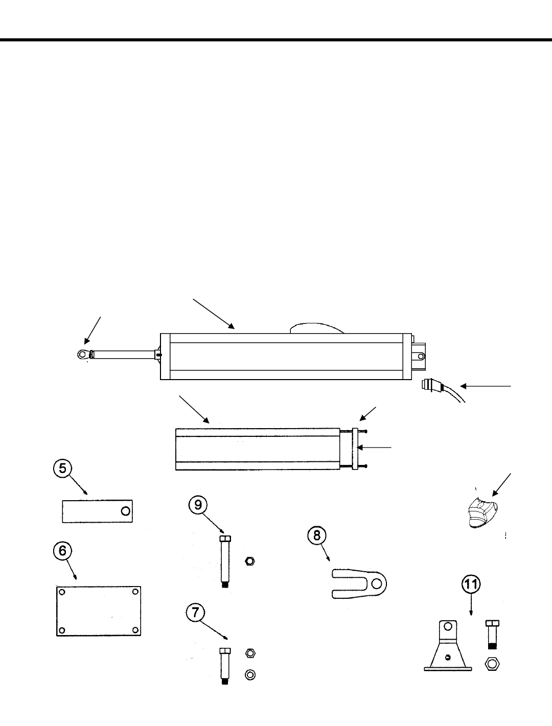
As you unpack the box, insure that all the following
parts included (see Figure 1). If you have ordered a kit
(a pair of operators), you will have twice the quantity
of parts listed below (except where noted).
1
400 Operator - 1 each
2
Protective Cover - 1 each
3
Protective Cover Tie-Rods - 2 each
4
Protective Cover End Cap - 1 each
5
Rear Mounting Bracket - 1 each
6
Rear Mounting Plate (optional) - 1 each
7
Short Brass Pin with 8mm nut and washer - 1 each
8
Rear Fork - 1 each
9
Long Brass Pin with 8mm self-locking nut - 1 each
10
Swivel joint with jam nut and washer - 1 each
11
Front mounting bracket with nut and bolt
12
Locking cap cover and key for Manual Release - 1 each
13
Electric Power Cord - 1 each
14
Manual Release Knob - 1 each
Figure 1. Parts of the 400 Operator
1
2
3
4
10
13
14