
User guide


RADIO
1-455D115 = 115V
1-455D = 230V
F2
F1
M
M
K
+OP -CL
+24 VFS W
NC -B -
STOP
A + TX
FS W
W. L.
LOCK
9 10 11 12 13 14 15 16 17 18 19
22 23 24 25
LAMPCOMOP CL
MOTOR 1
MOTOR 2
CLCOMOP
1 2 3 4 5 6 7 8
20 21
FC A 1
FC A 2
FCC2
FCC1
V1-4
61C455D
F-+
J2
J6
J4
J5
J1
J3
N L
MA IN
Page 15
February, 2009
400 Operator And
455 D Control Panel Installation Manual
CONNECT THE OPERATOR(S) TO THE
C
ONTROL PANEL
WARNING!
Turn the main power off before
you make any electrical connections or before
programming.
CAUTION: The operators are grounded only by
the grounded circuit the installer provides.
USING A JUNCTION BOX
If an operator is more than 2 ft away from the control
panel, you must use a junction box for connection.
Use a U. L. Listed cord grip where the operator cord
enters the junction box.
Note: If you have a one-leaf gate design, the
operator must be connected to Motor 1
(terminals 1,2, & 3)
To wire up motor 1, connect the white wire to
terminal 1(on the J4 terminal strip), the black wire to
2, and the red wire to 3. Wire each leg of the capacitor
(supplied) to terminals 2 & 3.
Note: If you want to delay the closing of one gate
leaf in a two-leaf gate design, be sure to connect
its operator to Motor 1.
In order to wire motor 2 in a bi-parting system,
connect the white wire to terminal 4 (on the J4
terminal strip), the black wire to 5, the red wire to 6.
Wire each leg of the capacitor (supplied) to terminals
5 & 6.
CHECK THE MOTOR’S DIRECTION OF
R
OTATION
WARNING! The pressure valves are not preset at
the factory and may operate a gate leaf with
enough force to endanger people and seriously
damage the gate leaf itself. Refer to your
operator’s installation manual to decrease the
hydraulic pressures before checking the motor’s
direction of rotation.
After you have connected the main power supply, and
the operator(s) to the control panel, you need to
check the direction of rotation for each operator
motor in your gate design.
Note: To check a motor’s direction of rotation,
you must have three closed circuits on terminal
block. Install one circuit between terminals 11
and 16 (already installed by factory), another
circuit between terminals “PHOTO OP/CL”, and
another circuit between terminals “PHOTO CL”.
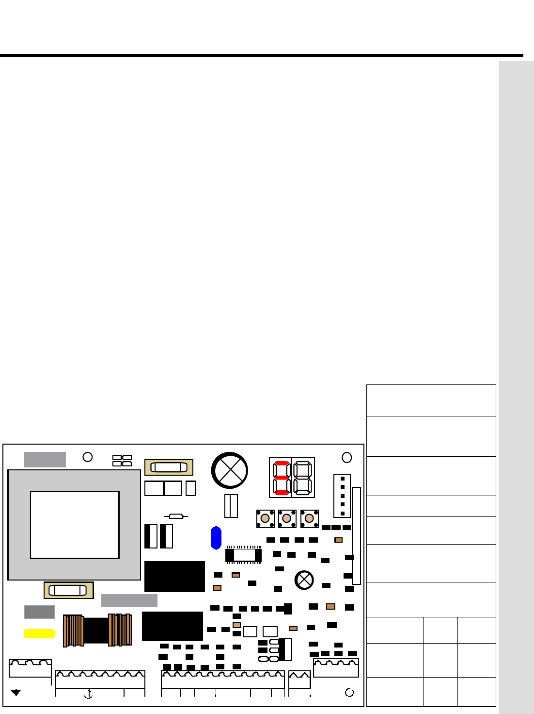
Figure 9. The 455 D Control Panel
J3 terminal block for main
power supply
J4 terminal block for
connecting the operator(s)
J1 terminal block for low-
voltage accessories
J2 quick connector port
F Function Push Button
— Programming Push
Button
+ Programming Push
Button
FUSES
220
VAC
115
VAC
F1
Main Power
5 A 10 A
F2
Accessories
800
mA
800
mA
THE 455 D CONTROL PANEL INSTALLATION INSTRUCTIONS