
User guide


Page 11
February, 2009
400 Operator And
455 D Control Panel Installation Manual
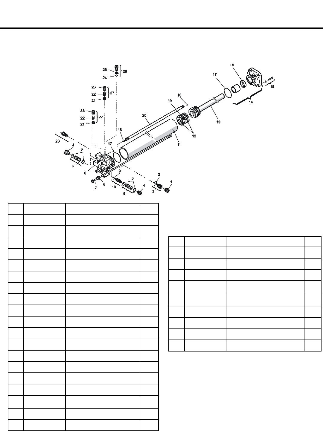
POS PART # DESCRIPTION QTY
1 7049005 Retainer (Brass) 4
2 N/A O-Ring (Inlet/Lock Valve) 5
3 4404065 Inlet Valve 1
5 4404085 Lock Valve (Bi-Metal) 2
6 4994655 Valve Body (2006) 1
7 7230295 Tie Rod (Cylinder) 4
8 N/A Star Washer 4
9 7090300015 O-Ring (Shuttle Piston) 1
10 4180285 Shuttle Piston 1
11 7366025 Cylinder 1
12 7091015 Seal (Piston) 2
13 4350105 Piston Assembly 1
14 4994625 Flange (Front) 1
15 N/A Seal (Front Flange) 4
16 N/A Bushing (Front Flange) 1
17 7090360025 O-Ring (Valve Body) 2
18 7090815 O-Ring (Retract Tube 06’) 2
19 N/A Center Ring (Piston) 1
4 7049005 Retainer (Brass) 4
POS PART # DESCRIPTION QTY
20 7361335 Retract Tube 1
21 4180415 Bi-Pass Assembly (06’) 2
22 4180415 Bi-Pass Assembly (06’) 2
23 4180415 Bi-Pass Assembly (06’) 2
24 7090280015 O-Ring (Manual Release) 1
25 N/A Spacer (Manual Release) 1
26 4180195 Manual Release 1
27 4180415 Bi-Pass Assembly (06’) 2
28 4404095 Inlet Valve (Bi-Directional) 1
EXPLODED VIEW, CYLINDER