
User guide


Page 10
February, 2009
400 Operator And
455 D Control Panel Installation Manual
BLEED THE OPERATOR
Air in the hydraulic fluid causes erratic performance in a
hydraulic system, so you must rid the 400 Operator of
that air to insure smooth operation.
In order to bleed the air out of the system, remove the
vent screw and simply run the operator with the
electronic control panel. The 400 will bleed itself.
INSTALLING THE 455 D CONTROL
P
ANEL
Locate the enclosure in the most convenient position
possible, considering the movement of the gate.
Installing the control panel consists of the following
general steps:
• Connecting the main power to the pre wired
enclosure
• Connecting the activating device
• Connecting the operator(s)
• Checking the direction of the motor's rotation
• Set operating modes
The installer is responsible for grounding the gate and
operator systems, for providing the main power breaker
switch, and for making sure that the entire gate system
meets all applicable electrical codes.
For the complete 455 D Control Panel Installation
Instructions, see pages 14—25 of this manual.
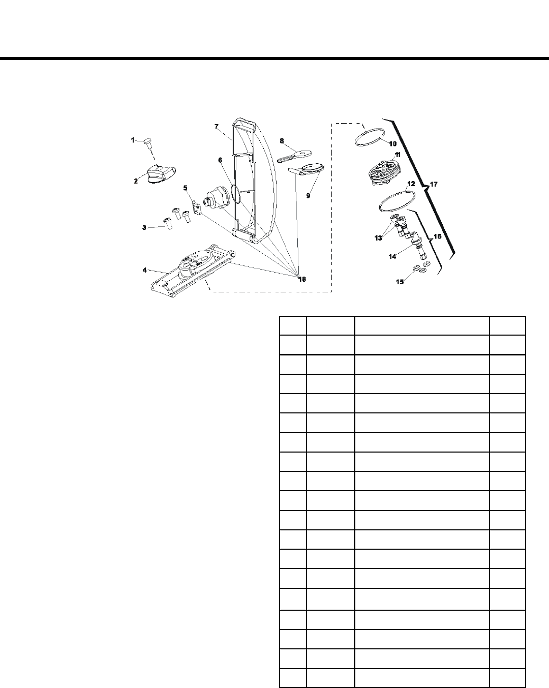
POS PART # DESCRIPTION QTY
1 701807 Screw (SS 4x8mm) 1
2 7290445 Knob (Release) 1
3 701526 Torx (SS T-20 Security) 3
4 720344 Main Body 1
5 729043 Lock Dog 1
6 7090895 O-Ring (Lock Cylinder) 1
7 7275285 Top Cover 1
8 7131005 Key (Viro) 1
9 7275275 Cap (Lock) 1
10 7090855 O-Ring (Receiver) 1
11 722795 Receiver 1
12 7090865 O-Ring (Bottom Cover) 1
13 718358 Bi-Pass Extensions 2
14 718359 Manual Release Extension 1
15 7090845 O-Ring (Extensions) 3
16 490327 Extensions Kit 1
17 490326 Receiver Kit 1
18 4185045 Locking Cap Assembly 1
EXPLODED VIEW, LOCKING CAP