
User's Manual

ITA ENG FRA ESP DEU POR
7 / 8
6-1620135 rev.1 08/07/2015
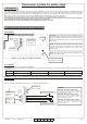
Through the dip switch Low Power present on the TCOO900 it is possible to limit the frequency with which it transmits its state of functioning (period of
interrogation): in this case it will be necessary to keep in consideration the dangerous condition that can be created if the power supply (battery) is
taken off from the TCOO900 during the interval of time before the successive transmission of its state and successively to the alarm from the safety
edge: in this case the RCOO900 will signal the alarm only after the period of interrogation.
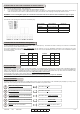
With the dip 3 of the TCOO900 on OFF: energy saving deactivated, it checks the state of the TCOO900 each second (Low Power deactivated)
With the dip 3 of the TCOO900 on ON: energy saving activated, it checks the state of the TCOO900 each 15 seconds (Low Power activated)
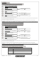
11. ENERGY SAVING (LOW POWER)
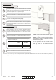
12. DEVICES TEST
Through the dip switch 1 of the RCOO900 it is possible to select if the device test must be carried out with a high logic signal (so the test will activate
itself if between the terminals TEST1 and TESTC will be present a tension from 10V dc to 24 Vdc) or with a low logic signal (so the test will activate
itself if between the terminals TEST1 and TESTC will be present a tension of 0Vdc). In this case, the test will be carried out for the device memorized
to the relay 1. The same is for TEST2 and TESTC for the device memorized to the relay 2.
With the dip 1 of the RCOO900 on OFF: the test of the device is executed by applying a high logic signal 10-24 Vdc at the input.
With the dip 1 of the RCOO900 on ON: the test of the device is executed by applying a low logic signal 0 Vdc at the input.
Note: in case you do not want to use the test of the device, place the dip 1 on OFF.
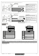
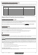
On each TCOO900, two keys, said “programming/test key”, and two leds are present. The pressure of the key of the safety edge that is tested during
the normal functioning (so not in programming) produces a signal that is sent to the receiver which close the contact of the relay and answers to this
signal with:
Number of BIP /
BLINK
Meaning
1 Regular functioning, no mistake found.
2 One or more sensitive edges on alarm.
3 One or more 8K2 sensitive edges disconnected.
Acoustic signaling during the normal functioning
4 Battery tension under the level of attention.
5 Battery tension under the minimum level.
6 One or more associated devices disconnected
What to do
-
Check the sensitive edges connected
Check the sensitive edges connected
Substitute the batteries of the indicted device
Substitute the batteries of the indicted device
Check each associated device
10. PROGRAMMING / TEST KEY OF THE TCOO900
Note: If one TCOO900 is in alarm but it necessary to open or close the automation in any case, it’s necessary to press and keep pressed the
programming / test button of the indicted TCOO900 and in the same time move the automation.
WARNING: If the batteries are completely flat, it will be necessary to change them.
13. FCC COMPLIANCE
This device complies with part 15 of the FCC rules. Operation is subject to the following two conditions: (1) This device may not cause harmful
interference, and (2) this device must accept any interference received, including interference that may cause undesired operation.
IMPORTANT! Any changes or modifications not expressly approved by the party responsible for compliance could void the user’s authority to operate
this equipment.
NOTE: This equipment has been tested and found to comply with the limits for a Class B digital device, pursuant to part 15 of the FCC Rules. These
limits are designed to provide reasonable protection against harmful interference in a residential installation. This equipment generates, uses and can
radiate radio frequency energy and, if not installed and used in accordance with the instructions, may cause harmful interference to radio
communications. However, there is no guarantee that interference will not occur in a particular installation. If this equipment does cause harmful
interference to radio or television reception, which can be determined by turning the equipment off and on, the user is encouraged to try to correct the
interference by one or more of the following measures:
•
Reorient or relocate the receiving antenna.
•
Increase the separation between the equipment and receiver.
•
Connect the equipment into an outlet on a circuit different from that to which the receiver is connected.
•
Consult the dealer or an experienced radio/ TV technician for help.
FCC Radiation Exposure Statement
This equipment complies with FCC radiation exposure limits set forth for an uncontrolled environment. This equipment should be installed and
operated with minimum distance 20cm between the radiator and your body.