
User's Manual

ITA ENG FRA ESP DEU POR
4 / 8
6-1620135 rev.1 08/07/2015
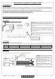
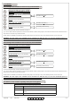
Depending on the type of signal required, connect the outputs as
explained in the following table:
OUTPUT SIGNAL USED TERMINAL
BOARD
SETTING OF
DIP SWITCH
N.C. contact
NC1-C1 (o NC2-C2) -
N.O. contact
NO1-C1 (o NO2-C2) DIP5 OFF (o DIP6 OFF)
8,2kΩ resistive
NO1-C1 (o NO2-C2) DIP5 ON (o DIP6 ON)
3
4
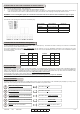
Fix the device as much higher than possible in such way as there are
no obstacles on the direction of the receiver and in such a way as the
maximum distance between the two devices is less than 15 meters
(max 20 meters).
2
Set the dip switch relative to the utilized frequency (DIP 4 and DIP 5)
which will have to correspond to the one of the RCOO900.
4. CONNECTIONS
4.1 TCOO900 connection
1
Connect the sensitive edge to the terminal boards of the device. Set
the dip switch relative to the type of the used safety edge (DIP 1, DIP
2 and DIP 6).
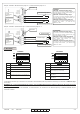
Orientate and put the device as explained in figure.
Give power to the system connecting the two batteries AA – 1,5 V to
the battery holder. Pay attention to the polarity .
2
3
4
Connect the test inputs to the control unit, in case they are utilized (*).
1
4.2 RCOO900 connection
Put the RCOO900 in such a way to minimize the distance from the
associated TCOO900 and close the to the automation’s control unit
or inside the box of the motor. If fixed to a wall, utilize suitable screws
and plugs so that it can resist to a force of 50N downwards.
Set the dip switch relative to the utilized frequency (DIP 3 and DIP 4)
which will have to correspond to the one of the TCOO900.
(*) The inputs are handled in the same way as the photocells test: the control unit, to carry out the photocells test, switches off the power supply of the
receiver and check that the relays of the correspondent receiver opens itself. In this device, the input TEST1 and TEST2 are for testing the security
devices (see paragraph 12).
WARNING : Allmatic can not be considered responsible
for any damages caused by an improper, incorrect or
irrational use of the product.
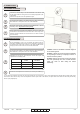
WARNING: keep free the areas of access to the devices
and clean periodically them from eventual dirtiness
which can settle on them during the normal
functioning.
WARNING: install the TCOO900 at minimum height of
20 cm from the ground.