
User's Manual

Registration number: W6M21409-14450-C-1
FCC ID: SU7300MCD21V2-CG
Worldwide Testing Services(Taiwan) Co., Ltd Page 19 of 19
3.9 Conducted Measurement at (AC) Power Line
For an intentional radiator which is designed to be connected to the public utility (AC) power line, the
radio frequency voltage that is conducted back onto the AC line on any frequency or frequencies within
the band 150 kHz to 30 MHz shall not exceed the limits in the table bellows with this provision shall be
based on the measurement of the radio frequency voltage between each power line and ground at the
power terminals.
This measurement was transact first with instrumentation using an average and peak detector and a 10
kHz bandwidth. If the peak detector achieves a calculated level, the measurement is repeated by an
instrumentation using a quasi-peak detector.
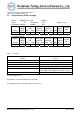
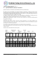
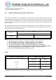
Level
Frequency
quasi-peak (dBµV/m) average (dBµV/m)
-- kHz -- --
Note
1. The formula of measured value as: Test Result = Reading + Correction Factor
2. The Correction Factor = Cable Loss + LISN Insertion Loss + Pulse Limit Loss
3. Detector function in the form : PK = Peak, QP = Quasi Peak, AV = Average
4. All not in the table noted test results are more than 20 dB below the relevant limits.
5. Measurement uncertainty = ±1.41 dB; Reported uncertainties represent expanded uncertainties
expressed at approximately the 95% confidence level using a coverage factor of k = 2.
6. This test is not required because the EUT is battery-used.
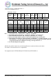
Limits:
Frequency of Emission (MHz) Conducted Limit (dBuV)
Quasi Peak Average
0.15-0.5 66 to 56 56 to 46
0.5-5 56 46
5-30 60 50
Test equipment used: ETSTW-CE 001, ETSTW-CE 003, ETSTW-CE 016, ETSTW-RE 045