
User's Guide


emerald Quick Installation Guide
15
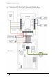
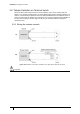
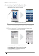
3.4.2 Wiring a voltage not provided lock (external power)
The emerald relays can be used to control a lock using a 12-24V DC,UL294 or UL603 listed
power supply.
Important
When using 24V power for a lock, it is imperative that the switch position is set to EXT. Setting the switch to INT
will result in 24V being supplied to the terminal which may cause irreversible damage.
This is the recommended wiring configuration when locks require 24V.
Figure 13 Illustration of wiring for lock with external power provided
3.4.3 Output power switch
Each of the two outputs has a switch that allows power to be provided to the output from the
terminal’s internal power circuit or by an external power source.
External power
When the switch is set to EXT a separate 12 - 24V DC,UL294 or UL603 listed power supply
must be used to provide power for any locks or other door furniture attached to the output.
Internal power
When the switch is set to INT, the lock or other load is powered by the terminal’s internal
supply. In this case the total load must not exceed 1.3A @ 12V.
Important
The terminal’s 12V connectors all link to the same circuit, powering the terminal and any outputs set to INT. It is
imperative that before attaching 24V to power an output checks should be made that the relevant output switch is
set to EXT. Applying 24V to an output with the switch set to INT will result in 24V being supplied to the common
power circuitry, potentially damaging the terminal.
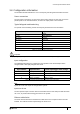
3.4.4 Supported third party read heads
UL approved emerald installations must only use listed read heads.
Read head Manufacturer product code
HID iClass SE R10 Smart Card Reader 6100/6108
HID iClass SE R30 Smart Card Reader 6110/6118
Table 10: Supported third party read heads