
User's Guide


11
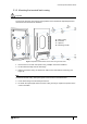
Chapter 3
Wiring the Terminal
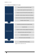
3.1 Cabling requirements
Table 6 outlines recommended cabling requirements for each connector on the emerald.
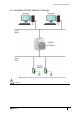
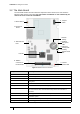
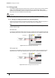
3.1.1 Ethernet host
Ethernet communications should be cabled & terminated for 100Base-T operation according to
IN ANSI/TIA/EIA-568-A / TIA/EIA-568-B. In order to comply with FCC requirements, a snap-on
ferrite (Wurth Electronics 74272722 or equivalent) should be used around the Ethernet cable.
Due to limited space, additional care should be taken when using CAT6 connectors or CAT5
connectors with a strain relief boot at the terminal. There should be enough spare cable left
within the enclosure/back box to allow a service engineer to open the terminal case without
straining the RJ45 connector. Where the cable is subject to movement or vibration, stranded
Ethernet cable (and appropriate connectors) should be used.
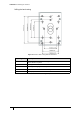
Purpose Recommended Cable Connector Max Length
External 12V
supply
Belden 8760 18AWG two
conductor cable or equivalent
14AWG Screw Terminal
Variable
a
10V
min
a. As a guideline, a maximum 2A load using 18AWG should travel no longer than 45m.
Inputs Belden 95XX or equivalent (XX =
the number of pairs from 01 - 50)
14AWG Screw Terminal 606m (2000’)
Outputs Belden 9462 or equivalent 14AWG Screw Terminal
Variable
b
b. As a guideline, a typical maglock from 650mA up to 1500mA @ 12V would use AWG18
cable, located no more than 7.6m (25’) from the emerald™ terminal.
Note
22AWG is the smallest acceptable cabling for a UL-294 installation.
Wiegand Belden 9514 (7 x 22AWG), Alpha
1229C(9 x 22AWG) or equivalent
14AWG Screw Terminal 60m (200’)
Table 6: Terminal installation cabling requirements
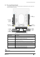
Type Recommended Cable Connector Max Length
Host CAT5/CAT5e/CAT6 RJ-45 Socket 100m (328’)
Table 7: Ethernet host