
User's Guide


emerald Quick Installation Guide
9
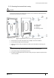
2.1.3 Mounting the terminal back casing
Important
The emerald terminal must be fitted on the secure side of the door.
To access the full range of mounting screw positions of the terminal the Input/Output board
must first be removed from the back box.
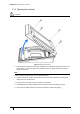
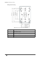
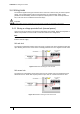
Figure 7 Exploded view illustration of the back casing and I/O board
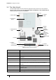
1. Remove the four screws and spacers using a Phillips star head screwdriver.
2. Lift the I/O board away from the mountings.
3. Drill the back outer casing as required for cable access and back box mounting. (see
Figure 8)
Note
To maintain the IP65 rating, waterproof glands must be fitted to the drilled holes.
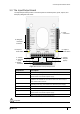
4. Fit the back casing to the electrical junction box.
5. Re-attach the input/output PCB to the back casing ensuring to replace the spacers in the
correct orientation.
A - Back casing
B - I/O board
C - Spacers
D - Mounting screws
C
C
D
D
D
D
A
C
B
C