
User's Manual
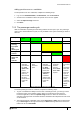
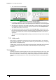
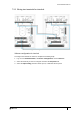
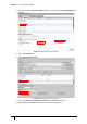
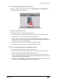
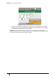
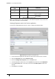
Table Of Contents
- Introduction
- Mounting the Terminal
- Wiring the Terminal
- 3.1 Cabling requirements
- 3.2 The front board
- 3.3 The input/output board
- 3.4 Wiring locks
- 3.5 Terminal with Request to Exit switch
- 3.6 Configuration information
- 3.7 Terminal with third-party OSDPv2 read head
- 3.8 Terminal with third-party Wiegand read head
- 3.9 Terminal with DIU 230 and third-party Wiegand read head
- 3.10 Configuration information
- 3.11 S700e with S700s exit reader
- 3.12 S700 with DIU 210 and S700s exit reader
- 3.13 S700 terminal with DIU 230
- 3.14 Tamper detection on reader inputs
- Reader Network Configuration
- AC2000 Software Configuration
- The System Configuration Menu
- S700 Operational Modes
- Appendix 1 Updating Firmware
- Appendix 2 Broadcast and Timezone Priorities
- Appendix 3 Loading card definitions

S700 Installation Manual
87
7.4 Equipment mode
A reader configured for Equipment mode must not be used to control a door lock.
The S700 reader controller can be used to enable third-party external equipment by using a
valid card swipe. The S700 enables the equipment; the actual control of the equipment is
carried out by the equipment. An S700 reader and exit combination can be used to enable two
independent pieces of equipment, for example, a generator or conveyor belt.
7.4.1 Setting up Equipment mode
The following outlines the hardware and software configuration for the Equipment mode on the
S700 reader and the AC2000 system.
Connections
The relay outputs on the S700 are used to enable equipment. The relays are low-voltage rated
contacts, so appropriately rated, interposing relays must be used if you want to enable mains-
powered equipment. The relays can either be configured as follows:
• To pulse at the start and pulse at the end of the required enable period
• To activate for the full duration of the required enable period
If necessary, the inputs on the S700 can be used to monitor feedback of the activation state
from the external equipment. Table 32: Equipment mode connections outlines the intended
usage of the available inputs and outputs.
Configuration
The configuration fields that are used by the Equipment enable mode are outlined in Table 33:
Equipment enable Timers.
Equipment
set
User
interaction
Connection
on the
Master
Purpose Comment
One Master Relay 1 Enable
equipment,
control
Low voltage switch
capable only
One Master Input 0 Equipment
activated, sense
Use volt-free
contacts on third-
party equipment
Two Exit Relay 2 Enable
equipment, Two
Low-voltage switch
capable only
Two Exit Input 1 Equipment
activated, sense
Use volt-free
contacts on third-
party equipment
Table 32: Equipment mode connections
Configuration
item
Abbreviation Comment
Lock open time LOT Mode start time, also stop relay time when
LOT2 is zero
Lock open time 2 LOT2 Non-pulsed relay and mode activation time
Table 33: Equipment enable Timers