
User's Manual
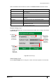
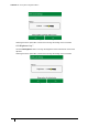
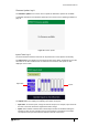
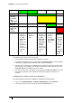
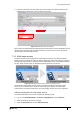
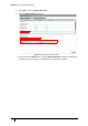
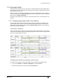
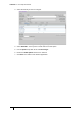
Table Of Contents
- Introduction
- Mounting the Terminal
- Wiring the Terminal
- 3.1 Cabling requirements
- 3.2 The front board
- 3.3 The input/output board
- 3.4 Wiring locks
- 3.5 Terminal with Request to Exit switch
- 3.6 Configuration information
- 3.7 Terminal with third-party OSDPv2 read head
- 3.8 Terminal with third-party Wiegand read head
- 3.9 Terminal with DIU 230 and third-party Wiegand read head
- 3.10 Configuration information
- 3.11 S700e with S700s exit reader
- 3.12 S700 with DIU 210 and S700s exit reader
- 3.13 S700 terminal with DIU 230
- 3.14 Tamper detection on reader inputs
- Reader Network Configuration
- AC2000 Software Configuration
- The System Configuration Menu
- S700 Operational Modes
- Appendix 1 Updating Firmware
- Appendix 2 Broadcast and Timezone Priorities
- Appendix 3 Loading card definitions

S700 Installation Manual
73
Firmware Update: key 8
The Firmware Update menu can be used to update the firmware if updates are available.
A complete description of the firmware update process can be found in Updating Firmware on
page 91.
Figure 49 Firmware Update
Inputs Tests: key 9
The S700 terminal has built-in tests that can be performed to check specific functionality.
The Input tests screen displays the four terminal inputs states. When peripherals such as the
exit reader or the Door Interface Unit are attached to the terminal, their inputs are also
displayed on the screen.
Figure 50 Inputs test
The Inputs test screen displays the following input states and inputs:
• Input state: To test the inputs, change the state of the input, for example, open and close
the door to test if the terminal is registered the state change.
• Inputs: Each number correlates with a terminal input number as detailed in Wiring the
Terminal on page 29. For example, input 0 is door position. The position of each input
corresponds to an input state, which is defined on the left of the screen.
Input state
Inputs