
User's Manual
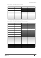
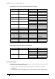


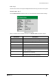
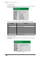
Table Of Contents
- Introduction
- Mounting the Terminal
- Wiring the Terminal
- 3.1 Cabling requirements
- 3.2 The front board
- 3.3 The input/output board
- 3.4 Wiring locks
- 3.5 Terminal with Request to Exit switch
- 3.6 Configuration information
- 3.7 Terminal with third-party OSDPv2 read head
- 3.8 Terminal with third-party Wiegand read head
- 3.9 Terminal with DIU 230 and third-party Wiegand read head
- 3.10 Configuration information
- 3.11 S700e with S700s exit reader
- 3.12 S700 with DIU 210 and S700s exit reader
- 3.13 S700 terminal with DIU 230
- 3.14 Tamper detection on reader inputs
- Reader Network Configuration
- AC2000 Software Configuration
- The System Configuration Menu
- S700 Operational Modes
- Appendix 1 Updating Firmware
- Appendix 2 Broadcast and Timezone Priorities
- Appendix 3 Loading card definitions

S700-IM-0088-1.72
CHAPTER 5 : AC2000 Software Configuration
62
Input table for S700 with DIU230 and S700s exit reader
Input table for four-state tamper configuration
5.4 Next steps
The S700 terminal is fully installed. The remainder of the manual details how to perform more
complex tasks with the terminal including:
• Using the system configuration menu to view maintenance information and perform
terminal tests
• Configuring the terminal in additional modes such as Passenger Mode and Door Control.
Input number Input function Sensor state AED alarm
0 Door position Open Door forced
Closed Door closed
1 Lock position Open Lock not engaged
Closed Lock engaged
2 Request to exit No default
3 Fire Open Fire alarm
Closed Fire alarm reset
4 Break glass Open Break glass
Closed Break glass reset
5 Mains power fail Open Mains power fail
Closed Mains OK
6 Battery low Open DIU battery low
7 DIU tamper switch Open DIU tamper
8 Spare No default
9 Spare No default
A Spare No default
B Spare / interlock No default
C Spare No default
D Spare No default
E Spare No default
F Spare No default
Table 25: S700e with DIU230 and S700s input alarms
Input number Input function Sensor state AED alarm
0 Door position Open Door forced
Closed Door closed
Tamper Input Tamper
1 Lock position Open Lock not engaged
Closed Lock engaged
Tamper Input Tamper
Table 26: Input table for four-state tamper configuration