
User's Manual
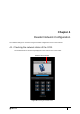

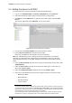
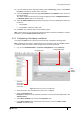
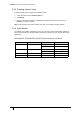
Table Of Contents
- Introduction
- Mounting the Terminal
- Wiring the Terminal
- 3.1 Cabling requirements
- 3.2 The front board
- 3.3 The input/output board
- 3.4 Wiring locks
- 3.5 Terminal with Request to Exit switch
- 3.6 Configuration information
- 3.7 Terminal with third-party OSDPv2 read head
- 3.8 Terminal with third-party Wiegand read head
- 3.9 Terminal with DIU 230 and third-party Wiegand read head
- 3.10 Configuration information
- 3.11 S700e with S700s exit reader
- 3.12 S700 with DIU 210 and S700s exit reader
- 3.13 S700 terminal with DIU 230
- 3.14 Tamper detection on reader inputs
- Reader Network Configuration
- AC2000 Software Configuration
- The System Configuration Menu
- S700 Operational Modes
- Appendix 1 Updating Firmware
- Appendix 2 Broadcast and Timezone Priorities
- Appendix 3 Loading card definitions

55
Chapter 5
AC2000 Software Configuration
This section of the manual focuses on the initial addition and configuration of the device and input
alarms. All other advanced configuration options are covered in the relevant function sections. The
S700 terminal is added to the AC2000 system and configured using the Devices application.
Note: This manual assumes access to the necessary AC2000 applications and should be
performed by persons trained in its use.
5.1 Reader addressing
The AC2000 system communicates with all devices on the access control network using the
CEM reader addressing system.
All devices are allocated a five-digit reader address, the address is displayed in the top right of
the terminal display.
Figure 32 Location of the reader address on the screen
Each digit of the reader address signifies a position on the Devices hierarchy.
Figure 33 Illustration describing AC2000 reader addressing
Reader address
RTC number ranges
from 00 - DE
Device group number 0 - F
Device number 0 - F
Master / Exit
0 = Master reader
1 = Exit reader