
User's Manual
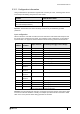
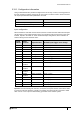
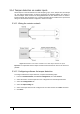

Table Of Contents
- Introduction
- Mounting the Terminal
- Wiring the Terminal
- 3.1 Cabling requirements
- 3.2 The front board
- 3.3 The input/output board
- 3.4 Wiring locks
- 3.5 Terminal with Request to Exit switch
- 3.6 Configuration information
- 3.7 Terminal with third-party OSDPv2 read head
- 3.8 Terminal with third-party Wiegand read head
- 3.9 Terminal with DIU 230 and third-party Wiegand read head
- 3.10 Configuration information
- 3.11 S700e with S700s exit reader
- 3.12 S700 with DIU 210 and S700s exit reader
- 3.13 S700 terminal with DIU 230
- 3.14 Tamper detection on reader inputs
- Reader Network Configuration
- AC2000 Software Configuration
- The System Configuration Menu
- S700 Operational Modes
- Appendix 1 Updating Firmware
- Appendix 2 Broadcast and Timezone Priorities
- Appendix 3 Loading card definitions

S700 Installation Manual
49
3.14.3 Re-assembling the terminal
To re-assemble the terminal, complete the following steps:
1. Ensure that there is adequate cable length available to reach the connectors comfortably
for each of the following:
– 12 or 24 Vdc
– CAT6 cable for communications
– Output wiring for lock
– Wiring for inputs, for example, door position sensor, lock sense
Important: To maintain the IP65 rating of the terminal, the cable access hole must be
adequately sealed before completing the installation process.
Note: Ensure the speaker is connected.
2. Attach the front pane of the terminal using the ribbon connector.
3. Attach the front of the terminal to the back casing and fix in places with the screws.
4. Attach the protective side panels to the terminal.
Note: If the terminal needs to be opened after installation, the side panels can be removed by
inserting an access card into the slot under the centre of the panel and sliding along the length
of the panel.