
User's Manual
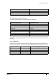
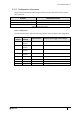
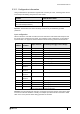
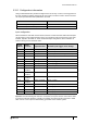
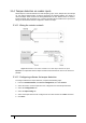
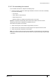

Table Of Contents
- Introduction
- Mounting the Terminal
- Wiring the Terminal
- 3.1 Cabling requirements
- 3.2 The front board
- 3.3 The input/output board
- 3.4 Wiring locks
- 3.5 Terminal with Request to Exit switch
- 3.6 Configuration information
- 3.7 Terminal with third-party OSDPv2 read head
- 3.8 Terminal with third-party Wiegand read head
- 3.9 Terminal with DIU 230 and third-party Wiegand read head
- 3.10 Configuration information
- 3.11 S700e with S700s exit reader
- 3.12 S700 with DIU 210 and S700s exit reader
- 3.13 S700 terminal with DIU 230
- 3.14 Tamper detection on reader inputs
- Reader Network Configuration
- AC2000 Software Configuration
- The System Configuration Menu
- S700 Operational Modes
- Appendix 1 Updating Firmware
- Appendix 2 Broadcast and Timezone Priorities
- Appendix 3 Loading card definitions

S700-IM-0088-1.72
48
3.14 Tamper detection on reader inputs
Terminal inputs can be monitored for 4-state tampering, open, close, tamper short, and tamper
cut. If an input is tampered with, an alarm is triggered in the AC2000 software. The alarm is a
universal tamper alarm and does not distinguish between the four different states. To monitor
inputs for tamper short and tamper cut, a resistor network must be installed on the input sensor
wiring and the AC2000 software configured to monitor the input.
3.14.1 Wiring the resistor network
Figure 27 Illustration of the resistor network for four state tamper detection on inputs
Important:
It is imperative that the tamper resistor network is wired as close to the sensor as
possible.
3.14.2 Configuring software for tamper detection
To configure software for tamper detection, complete the following steps:
1. From the AC2000 Floatbar, click Device Configuration, and click Devices.
2. Select the device on which inputs are to be configured for 4-state tamper detection.
3. Select the Configuration tab.
4. Select the Input Config tab.
5. Select each input element to be configured for four state and tick the 4 state check box.
6. Click Save.